Device for limiting the advance during a drilling operation

a drilling operation and advance technology, applied in the direction of manufacturing tools, portable drilling machines, wood boring tools, etc., can solve the problems of small depth, complicated refinishing, undesirable secondary effects, etc., and achieve the effect of preventing damage to the surface of workpieces

Inactive Publication Date: 2014-04-01
AIRBUS OPERATIONS GMBH
View PDF33 Cites 1 Cited by
  • Summary
  • Abstract
  • Description
  • Claims
  • Application Information

AI Technical Summary

Benefits of technology

[0007]Damage to the surface of workpieces is prevented by at least one aspect of the invention, so that corresponding refinishing is avoided. Moreover, the removal of the coiled chips from the drilling tool previously necessary after each drilling cycle is dispensed with.

Problems solved by technology

In this connection, on the one hand, too deep a countersunk recess may lead to rejects and, on the other hand, a countersunk recess with too small a depth makes complicated refinishing necessary.
It is a disadvantage of devices of the abovementioned kind that the chips produced lead to undesirable secondary effects depending on the material to be machined if the workpieces concerned have a sensitive surface.
This undesirable effect consists in that, in particular during drilling of the countersunk recess, flowing chips are produced, which wind themselves around the tool and in this way give rise to coiled chips or chip coils.
In this connection, the chip coils are whirled around the drilling tool, so that the rotating flowing chip wound around the drilling tool carries out uncontrolled movements and in doing so damages the surface of the workpiece to a greater or lesser extent by scratching.
Removal of the scratches produced in this way requires a considerable degree of extra work.
In addition, the operating sequence is disrupted by virtue of the chip coils having to be removed by hand after each drilling cycle.

Method used


Image

  • Device for limiting the advance during a drilling operation
  • Device for limiting the advance during a drilling operation
  • Device for limiting the advance during a drilling operation

Examples


Embodiment Construction

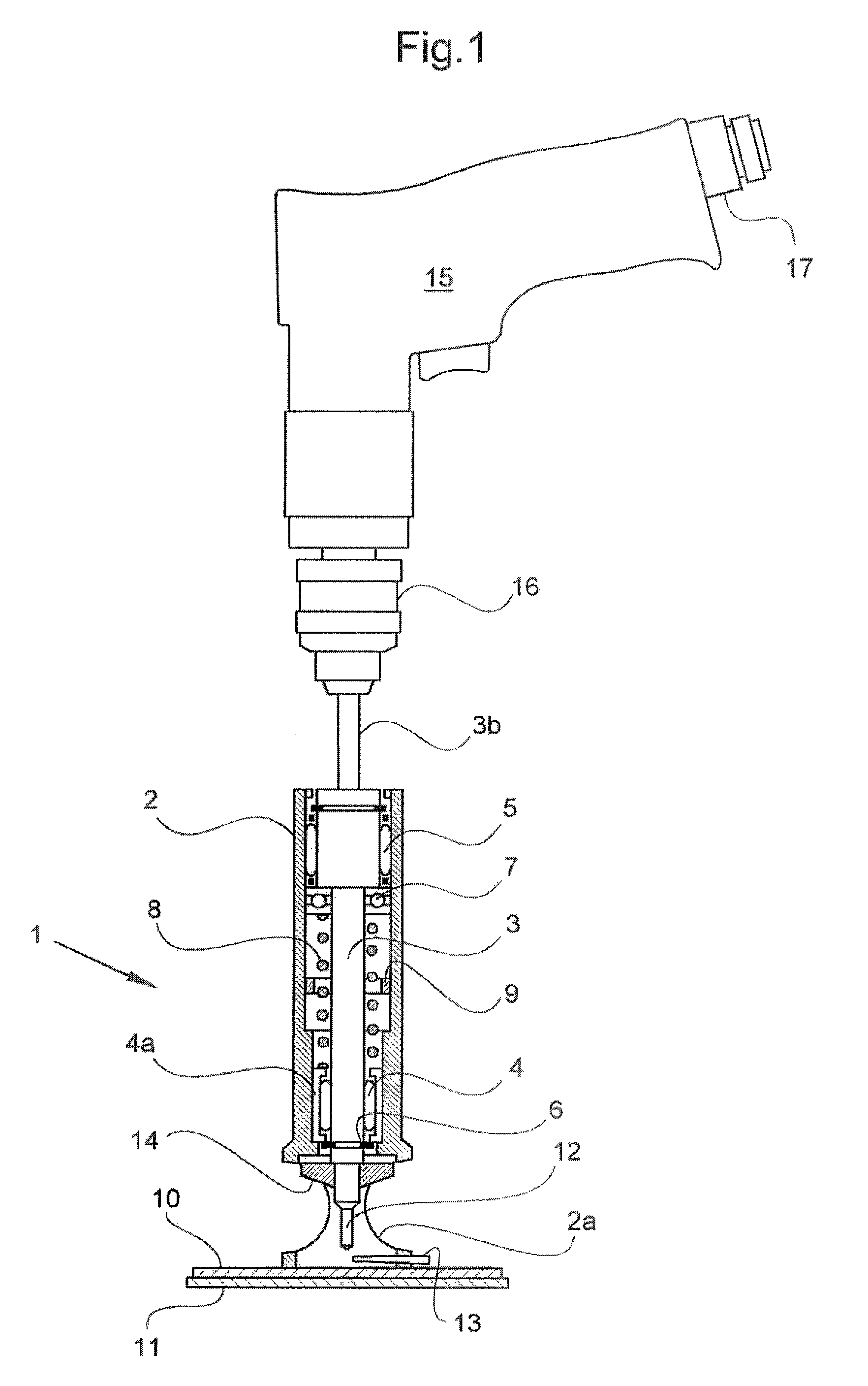
[0013]FIG. 1 shows a device 1 of a known kind for limiting the advance by way of example in conjunction with a hand drill, the device 1 comprising a housing 2 and, mounted rotatably therein, a spindle 3 with a widened part 3a and a shank part 3b. A lower needle bearing 4 and an upper needle bearing 5 serve for mounting the spindle 3. The spindle 3 is illustrated in its upper position. In this position, an axial retaining ring 6 arranged on the spindle 3 bears against that part 4a of the needle bearing 4 fixed to the housing. The lower end of the widened part 3a forms a shoulder against which a thrust ball bearing 7 bears. A compression spring 8, which is for its part supported with its lower end against the part 4a of the needle bearing 4 fixed to the housing, acts on this thrust ball bearing 7 from below in the diagram. A stop 9 which is adjustable in the axial direction is arranged inside the housing 2. The compression spring 8 is dimensioned in such a way that the spindle 3 is he...


PUM

PropertyMeasurementUnit
depthsaaaaaaaaaa
depthaaaaaaaaaa
forceaaaaaaaaaa

Abstract

In a device for limiting the advance during a drilling operation, which can be used in conjunction with a hand drill or with an automatic manufacturing machine, the device comprising a housing with a stop cage and a spindle mounted rotatably and axially displaceably in the housing, and a stop which is adjustable in the axial direction being arranged for limiting the advance, the invention consists in that the stop cage (2a) comprises a pin fixed to the housing for breaking the chips, with a housing-side end and a free end, in such a way that it extends approximately parallel and directly adjacent to the workpiece surface and approximately radially from the outside towards the drilling tool in such a way that its free end almost touches the countersink. Damage to the surface of workpieces is prevented by the invention, so that corresponding refinishing is avoided. Moreover, the removal of the coiled chips from the drilling tool previously necessary after each drilling cycle is dispensed with.

Description

FIELD OF THE INVENTION[0001]The invention relates to a device for limiting the advance during a drilling operation, the device being operable both in conjunction with a hand drill and with a numerically controlled automatic manufacturing machine.BACKGROUND OF THE INVENTION[0002]A device for limiting the advance during a drilling operation includes, for example, a cylindrical housing with a rotatably mounted spindle arranged coaxially therein with a drive-side end and a tool-side end, which has limited displaceability in the axial direction. The drive-side end of the spindle is designed in such a way that it can be clamped into a drill chuck of a hand drill or into a corresponding receiver of an automatic manufacturing machine. The tool-side end of the spindle is provided with an internal thread, into which an appropriate drilling tool can be screwed. What are known as stepped drill bits, which combine a drill bit and a countersink, are used as the drilling tool in conjunction with d...

Claims


Application Information

Patent Timeline
Patent Type & Authority Patents(United States)
IPC IPC(8): B23B47/34
CPCB23B47/34B23B2251/48B23B51/104B23B49/005Y10T408/8925Y10T408/18Y10T408/50Y10T408/5653
Inventor KRUSE, MATHIASCLAUSEN, ROLFGOOHSEN, THOMASHINTZE, WOLFGANG
Owner AIRBUS OPERATIONS GMBH
Why Eureka
Try Eureka