
Automated multiple point fastener driving system

Inactive Publication Date: 2006-05-02
CONSTR IND INNOVATIONS LLC +1
View PDF13 Cites 5 Cited by
  • Summary
  • Abstract
  • Description
  • Claims
  • Application Information

AI Technical Summary

Benefits of technology

[0014]One significant advantage of the present invention is the ability of the system of the invention to move the structural elements substantially continuously along a path on the apparatus and drive the fasteners into the elements at the appropriate locations while the elements are moving. Another advantage is the ability of the system of the invention to adjust to the variations in the size or sizes of the structural elements, and drive the fasteners at the appropriate places for the size of the component.

Problems solved by technology

One of the biggest challenges to producing such components on a production line is the significant variability in the sizes and shapes that may occur in the same type of structural component.
One example of this challenge is the large range of sizes and shapes for that roof support trusses that may be used on the same structure, especially, for example, in custom-built homes.
Thus, the significant variability of home design has made it more difficult to apply production line practices to the manufacture of components that would otherwise be stick built on site.
While large scale production of roof support trusses is becoming more common, large scale line production of other components, such as those for assembling the walls of the structures, including headers and beams for positioning over openings in the walls, has remained relatively limited due at least in part to the significant variability of the sizes and shapes of these wall components.
The most progress appears to be in beams that are constructed out of lumber (or composites) that are glued together to form the larger beam, but these components can be significantly more expensive and often require pre-ordering ahead of the time of use to be sure that the component is available for use at the appropriate time.
However, significant variations in the sizes of the building elements require significant resetting of the adjustments for each variation.

Method used


Image

  • Automated multiple point fastener driving system
  • Automated multiple point fastener driving system
  • Automated multiple point fastener driving system

Examples


Embodiment Construction

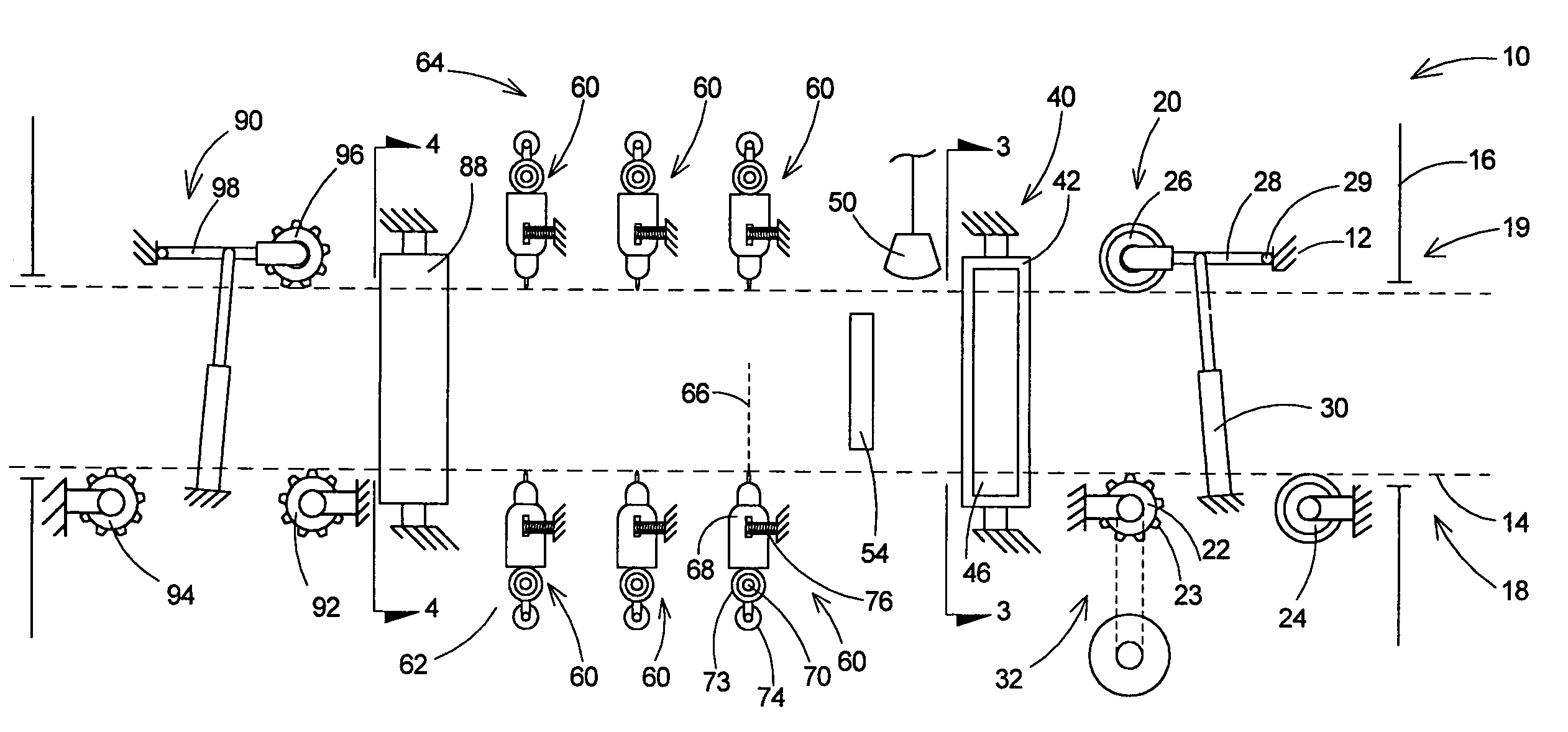
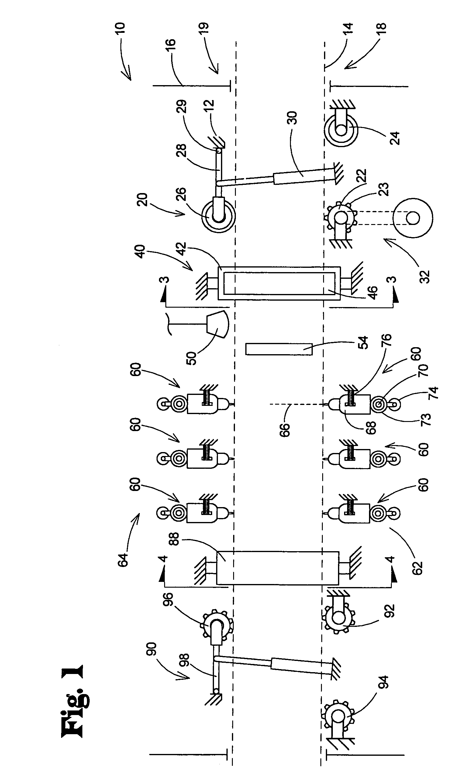
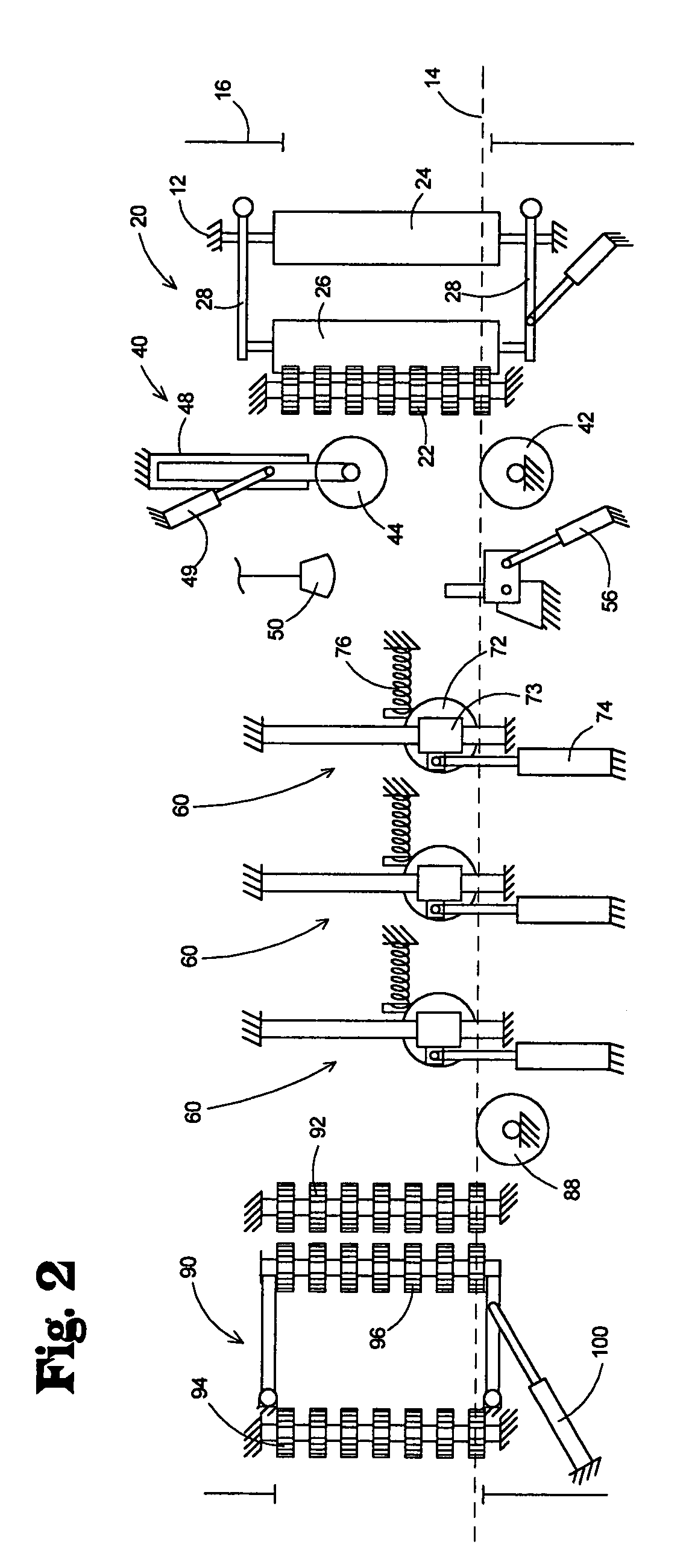
[0023]With reference now to the drawings, and in particular to FIGS. 1 through 6 thereof, a new automated multiple point fastener driving system embodying the principles and concepts of the present invention and generally designated by the reference numeral 10 will be described.

[0024]As best illustrated in FIGS. 1 through 6, the automated multiple point fastener driving system 10 generally comprises an entry clamping assembly 20 for clamping together the structural elements moving along the path, an alignment assembly 40 for pressing against the structural elements to substantially align at least one set of edges of the structural elements, fastener driver assemblies 60 for driving fasteners into the structural elements to connect them together, and an exit clamping assembly 90 for moving the connected structural elements out of the system.

[0025]As used herein, structural element is intended to include elements formed of any and all materials that may suitably used to form a structu...


PUM


Abstract

An automated multiple point fastener driving system is disclosed for driving fasteners into a plurality of structural elements for connecting the elements together while the elements are substantially continuously moving along a path The automated multiple point fastener driving system includes a frame with the path extending through the frame for movement of structural elements, a moving assembly for moving a plurality of structural elements along the path in a substantially continuous manner, an entry clamping assembly for clamping together the structural elements as the elements move substantially continuously along the path, an alignment assembly for aligning at least one edge of the plurality of structural elements as the elements move substantially continuously along the path, and fastener driving assembly for driving fasteners into the plurality of structural elements as the elements move substantially continuously along the path.

Description

BACKGROUND OF THE INVENTION[0001]1. Field of the Invention[0002]The present invention relates to automated fastener driving systems and more particularly pertains to a new automated multiple point fastener driving system for driving fasteners into a plurality of structural elements for connecting the elements together while the elements are substantially continuously moving along a path.[0003]2. Description of the Prior Art[0004]Traditionally, many components of structures, especially so-called “tick built” wood structures for home and businesses, have been assembled on the site at which the structure is to be erected. More and more, production of various components have been moved off-site to manufacturing facilities where the components for many structures are assembled on the same production line in an often more hospitable environment. One of the biggest challenges to producing such components on a production line is the significant variability in the sizes and shapes that may o...

Claims


Application Information

Patent Timeline
IPC IPC(8): B27F7/00
CPCB27F7/006
Inventor FREDRICKSON, CLYDE R.WISMER, MARKFREDRICKSON, DREW
Owner CONSTR IND INNOVATIONS LLC
Learn More