Electric powered pump

a technology of electric power and electric motor, which is applied in the direction of piston pumps, positive displacement liquid engines, liquid fuel engines, etc., can solve the problem of not achieving the cooling effect of sufficient amoun

Active Publication Date: 2006-05-02
AISIN SEIKI KK
View PDF20 Cites 35 Cited by
  • Summary
  • Abstract
  • Description
  • Claims
  • Application Information

AI Technical Summary

Problems solved by technology

With the construction of the known electric powered pump described in Japanese Patent Laid-Open Publication No. 2000-018173, a portion of the operational fluid is circulated adjacent to the driver using the hydraulic pressure pump to cool the driver, which does not achieve the sufficient cooling effect when the temperature of the operational fluid is high.

Method used


Image

  • Electric powered pump
  • Electric powered pump
  • Electric powered pump

Examples


second embodiment

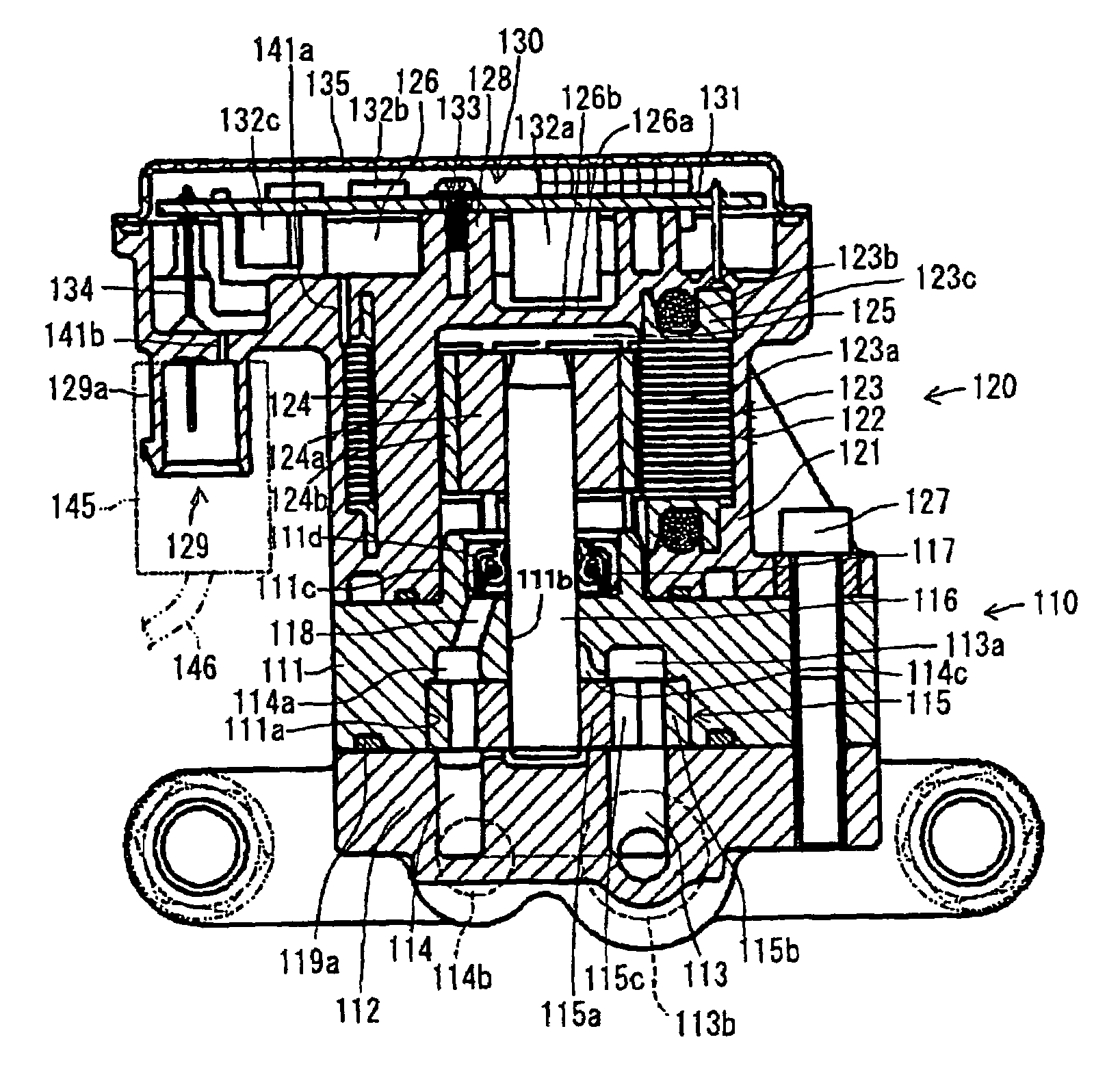
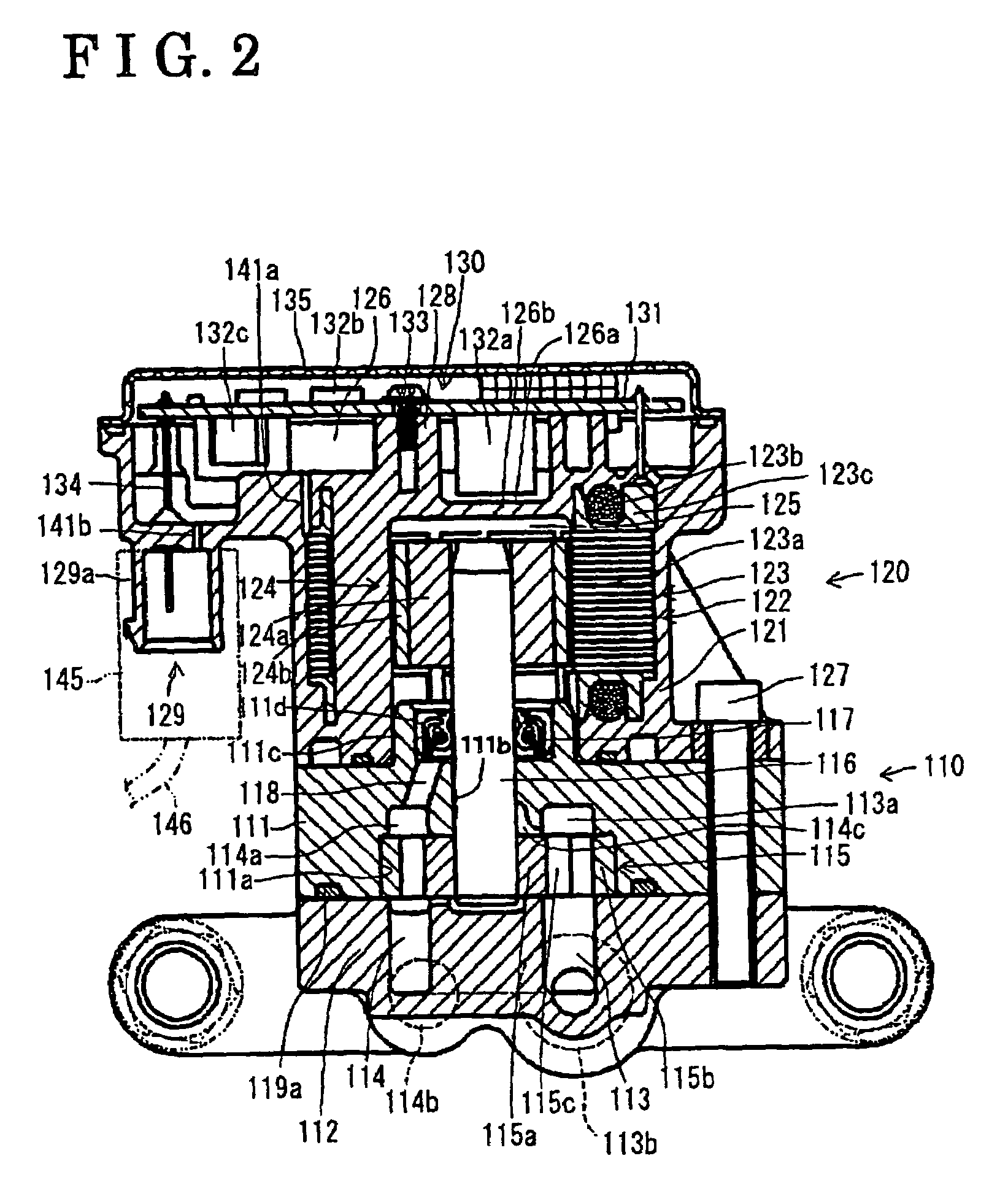
[0043]With the construction of the electric powered pump including the driver portion 130 for driving the motor portion 120 unitarily formed on the motor housing 121, the inside of the motor housing, i.e., the cylindrical space 125, is in communication with the outside of the motor housing 121 via the small clearance between the layered plates, made of iron or the like, of the core 123a of the brush-less DC motor 122, the first air vent 141a, the accommodation space 126, the second air vent 141b, and the harness 146 to be liquid tight. Accordingly in case the pressure in the motor housing 121 is significantly fluctuated, the generation of the pressure difference between the inside and the outside of the motor housing 121 is most likely prevented, thus to prevent the leakage of the water and the external objects via the clearance of the motor housing 121. Further, in case the air in the cylindrical space 125 moves into the accommodation space 126, the sprayed operational fluid is att...

third embodiment

[0047]the present invention will be explained with reference to FIGS. 5–6. The electric powered pump of the third embodiment shares the basic construction with the electric powered pump of the second embodiment. With the construction of the third embodiment, the driver potion 130 is separated from the motor housing 121 of the electric powered pump and a third air vent 241 is provided instead of the first and the second air vents 141a, 141b of the second embodiment. The explanations for the shared construction with the second embodiment will not be repeated.

[0048]The motor housing 221 made of resin is configured to be cylindrical having a bottom. The motor housing 221 includes a core 223a made from layered plates of magnetic body such as layered iron plate, and a stator 223 including a coil wound around a coil support frame, which are unitarily molded. The cylindrical space 125 having the bottom is formed at a portion inside of the stator 223 of the motor housing 221. The internal su...


PUM


Abstract

An electric powered pump includes a pump body having a suction chamber, a discharge chamber and an accommodation concave portion for accommodating a pump rotor, a rotational shaft rotatably supported by the pump body, the pump rotor is fixed at a first end of the rotational shaft, a motor having a rotor including a magnet, an annular stator including a core and a coil, the rotor is fixed at a second end of the rotational shaft which is opposite to the first end of the rotational shaft, a motor housing having a hole shaped cylindrical space inside of the stator formed with the motor housing, the motor housing is fixed at the pump body to be positioned in the cylindrical space having a predetermined clearance relative to the rotor, a driver portion for driving the motor, a accommodation space formed at an end surface of the motor housing provided at a side of the second end of the rotational shaft, the accommodation space is configured to accommodate the driver portion, and a cover for covering the accommodation space.

Description

CROSS REFERENCE TO RELATED APPLICATIONS[0001]This application is based on and claims priority under 35 U.S.C. §119 to Japanese Patent Application No. 2003-151419, filed on May 28, 2003, Japanese Patent Application No. 2003-151421, filed on May 28, 2003, and Japanese Patent Application No. 2004-156311, filed on May 26, 2004, the entire contents of which are incorporated herein by reference.FIELD OF THE INVENTION[0002]This invention generally relates to an electric powered pump. More particularly, the present invention pertains to an electric powered pump used as a sub-pump for oil pressure supply to clutch elements in transmission of idling stopped automobile, or for cooling oil supply to a motor of Electric powered vehicle.BACKGROUND[0003]A known electric powered pump unitarily includes a hydraulic pressure pump, an electric motor for driving the hydraulic pump, and a driver unitarily provided on the electric powered motor for controlling the driving electric current applied to the ...

Claims


Application Information

Patent Timeline
Patent Type & Authority Patents(United States)
IPC IPC(8): F04B53/00H02K9/18F04C2/10F04C11/00F04C15/00H02K5/128H02K11/04
CPCF04C2/102F04C11/008H02K11/048H02K5/128F04C15/008H02K7/14H02K2211/03H02K11/33
Inventor SUZUKI, SHIGEMITSUISHIGURO, MOTOHISATERAYAMA, MITSURUUNNO, ATSUSHIKAJINO, HIROSHI
Owner AISIN SEIKI KK
Why Eureka
Try Eureka