Illuminated key blank

a technology of illumination and key blanks, applied in the field of keys, can solve the problems of limited or no commercial success, ruined locks, user stranded on the wrong side of locks, and likely not being undertaken by a locksmith

Active Publication Date: 2006-05-02
ELEMENT EXTREME
View PDF28 Cites 27 Cited by
  • Summary
  • Abstract
  • Description
  • Claims
  • Application Information

AI Technical Summary

Benefits of technology

[0009]It is an object of the invention to provide an illuminated key blank that is easy and inexpensive to manufacture.
[0011]It is another object of the invention to provide an illuminated key blank that is structurally sound and will not deform or break during use.
[0013]It is another object of the invention to provide an illuminated key blank that will enable the user to identify specific keys quickly and in the dark from among a plurality of keys.
[0014]It is another object of the invention to provide a method for making an illuminated key blank that is cost effective and easy to perform.
[0020]The invention also includes a set of keys including at least two such key blanks as described above. A first key blank includes a first casing of a first color, and the second key blank includes a second casing of a second color different from the first color. As above, at least one of the first and second light sources shines light that is substantially the same color as (or a contrasting color to) its respective casing. In this way, a person may not only use the keys in the dark, the person can identify which key is which in the dark as well (simply color-coding the casings does the user little good in poor lighting conditions, under which all colors tend to appear grey to the eye).

Problems solved by technology

Several have tried this approach in the past with limited or no commercial success.
Failure of such a two-piece device is potentially catastrophic, since the head will separate from the blade while the blade is inserted into the lock, thereby potentially ruining the lock and stranding the user on the wrong side of the lock.
The drawback to this device and method is that it requires the locksmith to purchase a specialized metal hole punch for punching a hole into the head of the key as desired.
Such an expense will likely not be undertaken by a locksmith and is not market-friendly, as it adds significant labor to each key-cutting operation and takes up room in the locksmith's workshop.
With such a system, the locksmith is committing to an expensive system from which he would likely not derive substantial sales sufficient to justify the cost of the system.
Finally, many of the prior devices are simply not secure and include a great number of customized components.
The greater the number of components, the more expensive the final product.

Method used


Image

  • Illuminated key blank
  • Illuminated key blank
  • Illuminated key blank

Examples


Embodiment Construction

[0031]Description will now be given of the invention with reference to the appended FIGS. 1–7. It should be noted that these drawings are exemplary in nature and in no way serve to limit the scope of the invention, which is defined by the claims appearing hereinbelow.

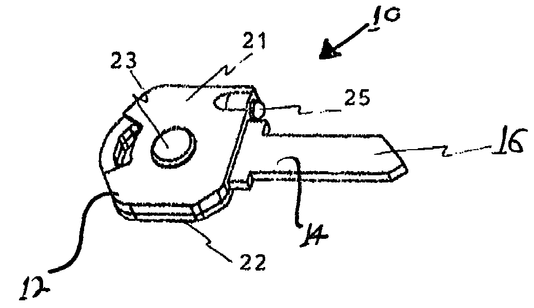
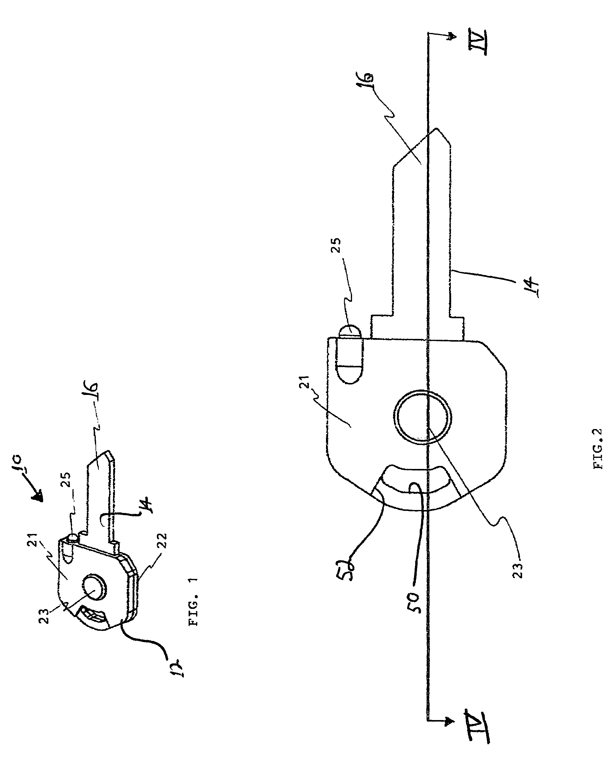
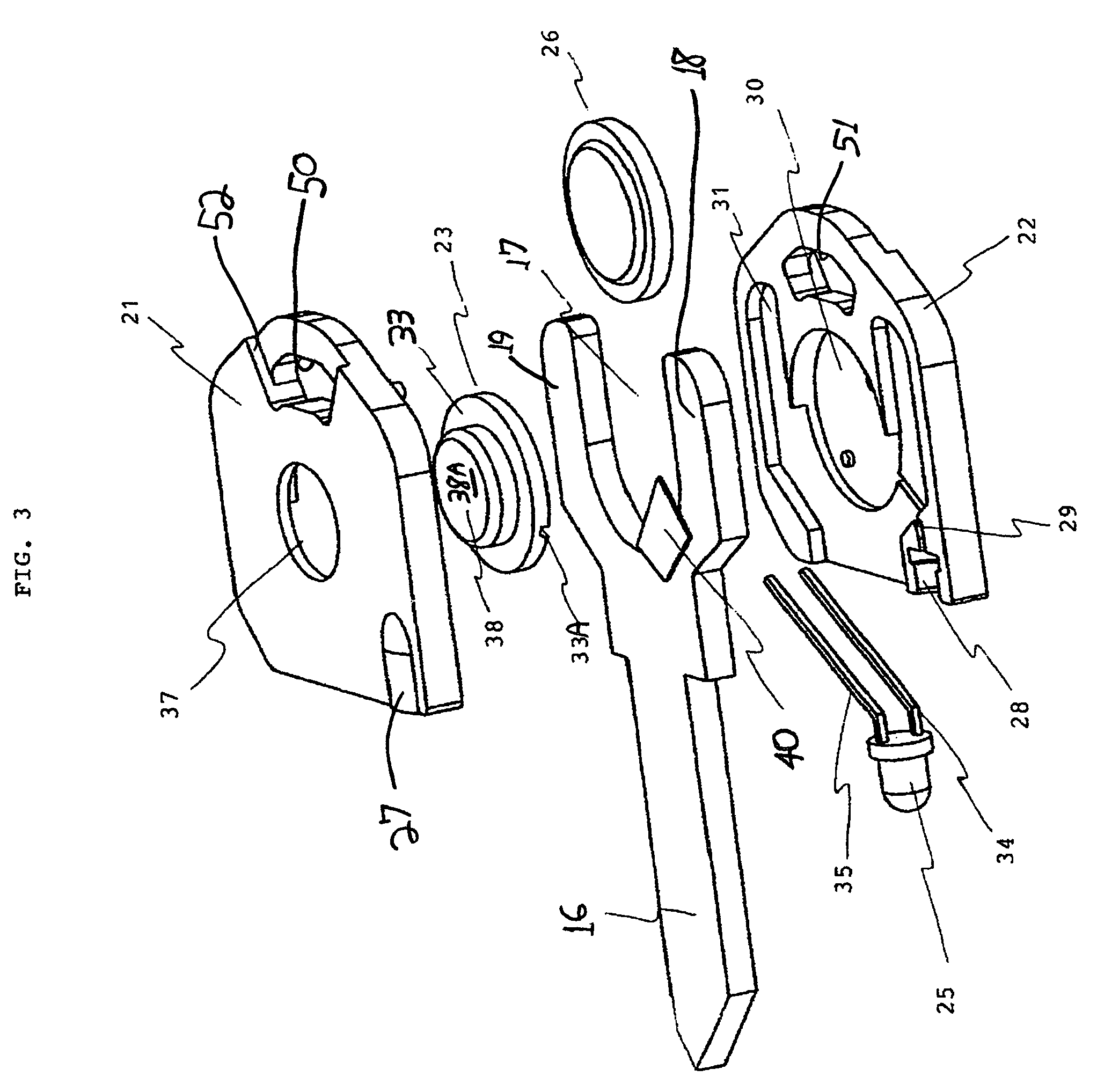
[0032]As shown in FIGS. 1–4, the main sections of the inventive key blank 10 are casing 12 and blank body 14. Blank body 14 includes a blade portion 16 and a head portion 18. Blade 16 and head 18 function as in conventional keys, i.e., blade 16 is to be cut to open a lock when inserted therein and head 18 forms a handle for the user to turn the key in the lock and to retain the key on a key ring or chain. Blade 16 and head 18 are integral with one another; that is, there is no connective or securing means that attaches the head to the blade. They are formed from the same piece of material, preferably metal. As best shown in FIG. 3, head 18 is preferably U-shaped and includes two arms 19 surrounding a cutout 17. Blank bo...


PUM


Abstract

An illuminated key blank is provided with a blade and a head integral with the blade as a single piece. A cutout is preferably formed in the key blank head so that the head is substantially U-shaped, and a battery is disposed in the cutout between the arms of the U. A light source, preferably a light-emitting diode (LED), is selectively electrically connected to the battery. A casing is sealed around the head of the key and the battery, and the casing retains the light source in place so that the light source shines light substantially in the direction of the blade. The light source shines light which is preferably the same or a contrasting color as the color of the casing so that the key may be identified in the dark.

Description

RELATED APPLICATIONS[0001]This claims domestic priority from U.S. provisional patent application No. 60 / 450,914 filed Mar. 3, 2003 and incorporates by reference all of its teachings herein.BACKGROUND OF THE INVENTION[0002]1. Field of the Invention[0003]The invention relates to keys, and more specifically to a combination key blank with light source.[0004]2. Description of the Related Art[0005]Keys used to open locks are universally known and come in a multitude of different shapes and sizes. It is common that one needs to open a lock under dim or darkened conditions. As such, it would be advantageous to provide a light source attached to or built into a key so that it may illuminate the darkened lock and facilitate the opening of the lock.[0006]Several have tried this approach in the past with limited or no commercial success. For example, U.S. Pat. No. 4,276,582 to Burnett; U.S. Pat. No. 4,392,186 to Cziment; U.S. Pat. No. 4,521,833 to Wolter; U.S. Pat. No. 5,541,817 to Hung; and U...

Claims


Application Information

Patent Timeline
Patent Type & Authority Patents(United States)
IPC IPC(8): E05B17/10
CPCE05B17/10
Inventor FREEMAN, DANIELFREEMAN, ARI
Owner ELEMENT EXTREME
Why Eureka
Try Eureka