Roller bearing oil feed device

a technology of roller bearings and oil feed, which is applied in the direction of roller bearings, mechanical devices, gearing, etc., can solve the problems of fretting wear on the side of the inner rings, oil will not penetrate to the contact locations, etc., and achieve the effect of preventing fretting wear

Inactive Publication Date: 2006-05-02
ISUZU MOTORS LTD +1
View PDF23 Cites 24 Cited by
  • Summary
  • Abstract
  • Description
  • Claims
  • Application Information

AI Technical Summary

Benefits of technology

[0014]The present invention was made in view of the above problems, its object being to prevent fretting wear in the locations of contact of the rolling elements and the inner ring in cases where the outer ring and the inner ring of the roller bearing rotate in synchronization.
[0020]According to the present invention, the outlet of the oil feed passage opens in a position which is immediately next to the locations of contact of the rolling elements and inner ring of each row i.e. is adjacent thereto in the axial direction, so supply of oil is effected from this position and an ample amount of oil is carried over to these locations of contact. Ample lubrication of these contact locations can thereby be achieved even when the outer ring and the inner rings are rotating in synchronization, making it possible to prevent fretting wear.

Problems solved by technology

Also, since the oil feed holes 32 of the spacer 24 are provided with a prescribed separation in the circumferential direction, there is a possibility that, between oil feed holes 32 that are adjacent in the circumferential direction, oil will not sufficiently penetrate to the contacting locations at positions which are more remote in the axial direction; this too tends to cause fretting wear on the side of the inner rings.

Method used


Image

  • Roller bearing oil feed device
  • Roller bearing oil feed device
  • Roller bearing oil feed device

Examples


Embodiment Construction

[0027]Preferred embodiments of the present invention are described below in detail with reference to the appended drawings.

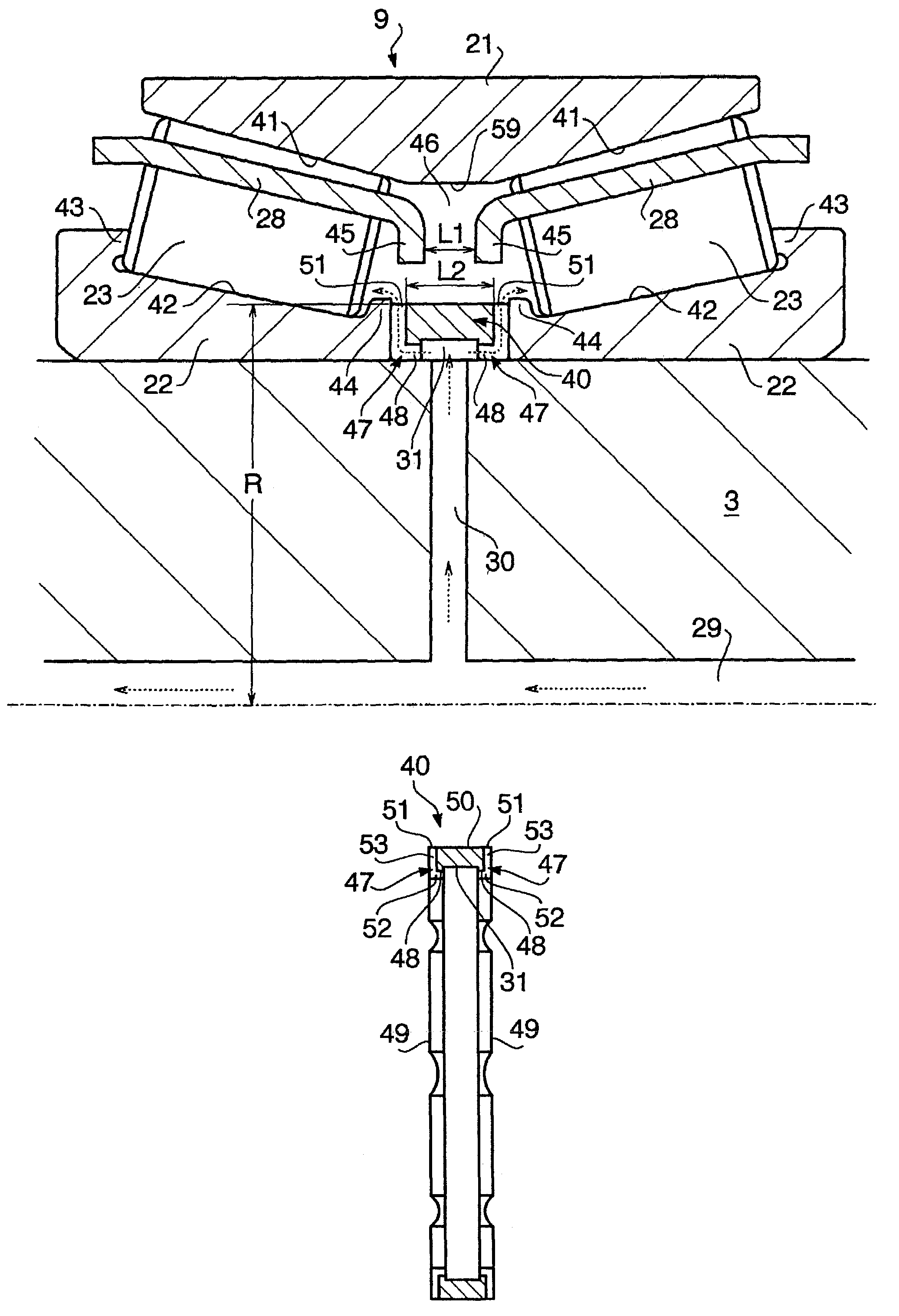
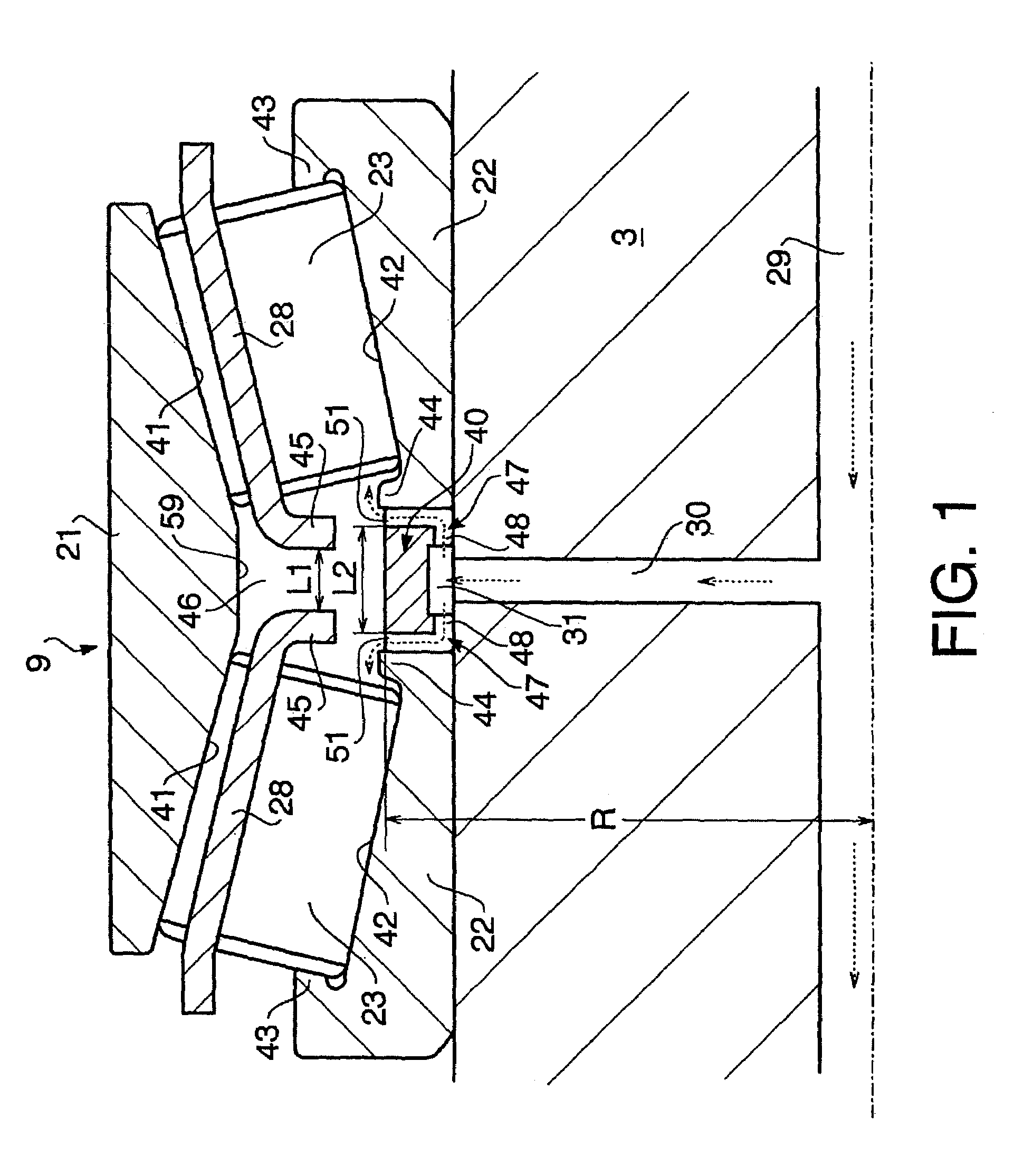
[0028]FIG. 1 shows a roller bearing oil feed device according to the present embodiment. This oil feed device is also applied to the splitter section of the transmission shown in FIG. 5; FIG. 1 shows the vicinity of the roller bearing to a larger scale. Structural items which are similar to those described above are given the same reference symbols and suitable supplementary description is added.

[0029]As shown in FIG. 1, the roller bearing 9 comprises an outer ring 21 as described above, two inner rings 22, 22, rolling elements 23 consisting of two rows in the axial direction, in each of which a plurality of rollers are arranged in the circumferential direction, and two holders 28. A spacer 40 is interposed between the inner rings 22, 22. This spacer 40 is different from the spacer 24 described above.

[0030]The roller bearing 9 is symmetrically constructed about ...


PUM


Abstract

A roller bearing oil feed device includes a plurality of rolling elements arranged in a plurality of rows in the axial direction between an outer ring and an inner ring, the inner ring being divided for each row of the rolling elements and a ring-shaped spacer being interposed at the position of this division, the inner rings and spacer being fitted onto a rotary shaft. A circumferential groove is provided in the inner peripheral section of the spacer and oil feed holes communicating with the circumferential groove are provided in the rotary shaft. An oil feed passage having an inlet opening into the circumferential groove and an outlet opening to a corner on at least one side in the axial direction of the spacer is provided in the spacer.

Description

BACKGROUND OF THE INVENTION[0001]1. Field of the Invention[0002]The present invention relates to a roller bearing oil feed device and in particular relates to a roller bearing oil feed device that is suitable for use with a splitter section of a manual transmission for a vehicle.[0003]2. Description of the Background[0004]FIG. 5 shows a splitter section (primary gear-change section) that is positioned most on the input side of a manual transmission for a vehicle. This transmission comprises an input shaft 1 whereby engine drive is transmitted and a main shaft 3 within the input shaft 1 whereby one end thereof is freely relatively rotatably and coaxially supported by means of needle bearings 2. The input shaft 1 is freely rotatably supported in a transmission case 4 by means of bearings 5. A counter shaft6 is arranged in parallel with the input shaft 1 and main shaft 3 below the input shaft 1 and main shaft 3. The counter shaft 6 is also freely rotatably supported by means of bearing...

Claims


Application Information

Patent Timeline
Patent Type & Authority Patents(United States)
IPC IPC(8): F16C19/00F16C19/40F16C19/38F16C33/60F16C33/66F16H3/091F16H57/04
CPCF16C19/386F16C33/60F16C33/6677F16H57/04F16C33/6681F16C2361/61F16H3/0915
Inventor TAKI, MASAFUMIITO, TAKASHITSUJIMOTO, TAKASHI
Owner ISUZU MOTORS LTD
Why Eureka
Try Eureka