Two-piece EMI shielding vent panel

a vent panel and shielding technology, applied in ventilation panels with screening provisions, ventilation casings, electric apparatus casings/cabinets/drawers, etc., can solve the problems that the current construction of vent panels does not facilitate the use of honeycomb vent panels in commercial applications, and the construction of vent panels still requires significant metal work, so as to achieve a simple and efficient construction

Inactive Publication Date: 2006-05-02
LAIRD TECHNOLOGIES LTD
View PDF7 Cites 33 Cited by
  • Summary
  • Abstract
  • Description
  • Claims
  • Application Information

AI Technical Summary

Benefits of technology

[0009]Advantageously, the EMI vent panel of the present invention provides a simpler and more efficient construction than achieved with prior art vent panels by avoiding th

Problems solved by technology

One significant factor affecting costs is that the frames for such shielding vent panels are produced from welded aluminum extrusions.
Unfortunately, current vent panel constructions do not facilitate the use of these honeycomb vent panels in commercial applications due to manuf

Method used


Image

  • Two-piece EMI shielding vent panel
  • Two-piece EMI shielding vent panel
  • Two-piece EMI shielding vent panel

Examples


Embodiment Construction

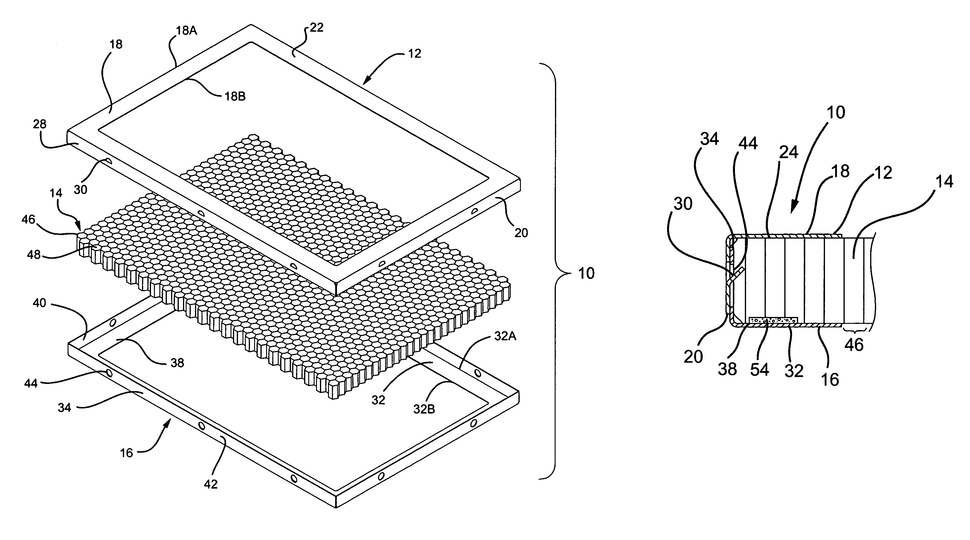
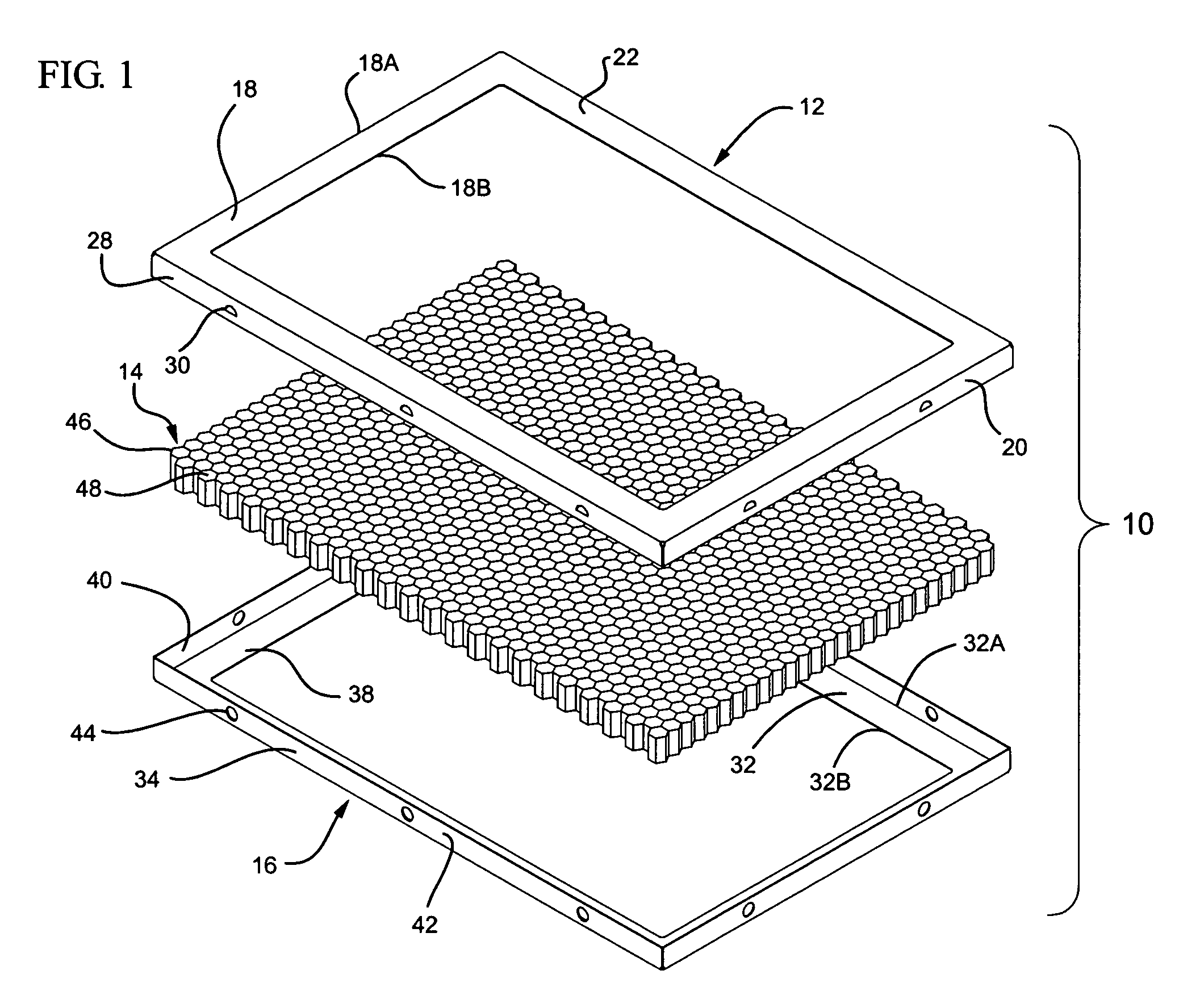
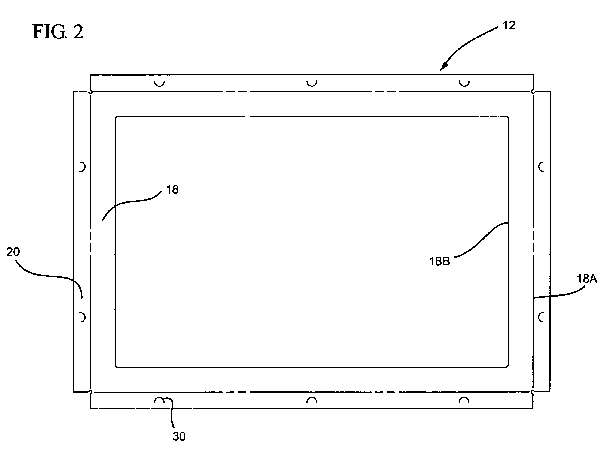
[0020]Referring to FIG. 1, a preferred embodiment of a two-piece electromagnetic interference (EMI) shielding vent panel 10 is illustrated. Vent panel 10 is adapted for use with a corresponding aperture of electronic equipment housing in which shielding from EMI is desired. As shown in FIG. 1, vent panel 10 includes a first frame piece 12 and a second frame piece 16 with an electrically-conductive filtering media 14 disposed therebetween. Advantageously, the use of a two-piece frame 12 and 16 allows for a simpler and more efficient assembly as compared to single-piece frames used in the art.

[0021]Frame pieces 12, 16 and media 14 are shown in FIG. 1 having generally rectangular dimensions. However, as will be recognized by those skilled in the art, frame pieces 12, 16 and media 14 can have any polygonal geometry sized to enclose a similarly dimensional vent opening (or aperture) in the housing for electronic equipment.

[0022]As shown in FIG. 1, first frame piece 12 include side walls ...


PUM


Abstract

An EMI shielding vent panel is provided for electronic equipment housings. The vent panel advantageously provides a simple and efficient construction through the use of a two-piece frame.

Description

[0001]This application claims priority under 35 U.S.C. §119(e) from Provisional Application No. 60 / 427,400 filed Nov. 19, 2002, which is herein incorporated by reference.FIELD OF THE INVENTION[0002]The present invention relates to two-piece EMI shielding vent panels and more particularly to two-piece EMI shielding vent panels having a honeycomb structured filtering media.BACKGROUND OF THE INVENTION[0003]The use of vent panels for shielding electronic devices from electromagnetic interference (“EMI”) has been known for years. Typically, the vent panels utilize a filtering media being an electrically conductive (e.g., metallic) honeycomb structure, which is particularly effective in dissipating EMI from electronic equipment.[0004]EMI shielding vent panels have found wide application in military equipment and high-performance electronic test equipment, where cost considerations are outweighed by performance requirements such as shielding effectiveness and ruggedness. One significant fa...

Claims


Application Information

Patent Timeline
IPC IPC(8): H05K9/00
CPCH05K9/0041
Inventor SOSNOWSKI, ANTHONY
Owner LAIRD TECHNOLOGIES LTD
Why Eureka
Try Eureka