Ion cyclotron resonance mass spectrometer

a mass spectrometer and cyclotron technology, applied in mass spectrometers, particle separator tube details, separation processes, etc., can solve the problems of reducing the usable volume of cyclotron movement, reducing mass resolution, and complicated electric field formed by trapping electrodes, and achieves the effect of higher ion capacity

Active Publication Date: 2006-05-02
BRUKER DALTONIK GMBH & CO KG
View PDF8 Cites 17 Cited by
  • Summary
  • Abstract
  • Description
  • Claims
  • Application Information

AI Technical Summary

Benefits of technology

[0015]the trap is not producing magnetron oscillations, simplifying detection and mass calculation, and increasing mass resolution;
[0017]the trap has a much higher ion capacity: it can store much more ions before mass shifts and resolution losses appear due to space charge effects, because the ions are spread evenly in a much larger volume along the axis of the ICR trap.

Problems solved by technology

Outside the axis of the ICR trap, the electric field formed by the trapping electrodes is more complicated and necessarily shows electrical field components in radial direction, as the detection and excitation electrodes usually have no DC voltages.
The superposition of the magnetron oscillation and the cyclotron oscillation is, in principle, a nasty effect introducing a frequency shift, diminishing the usable volume for the cyclotron movement, and reducing the mass resolution.

Method used


Image

  • Ion cyclotron resonance mass spectrometer
  • Ion cyclotron resonance mass spectrometer
  • Ion cyclotron resonance mass spectrometer

Examples


Embodiment Construction

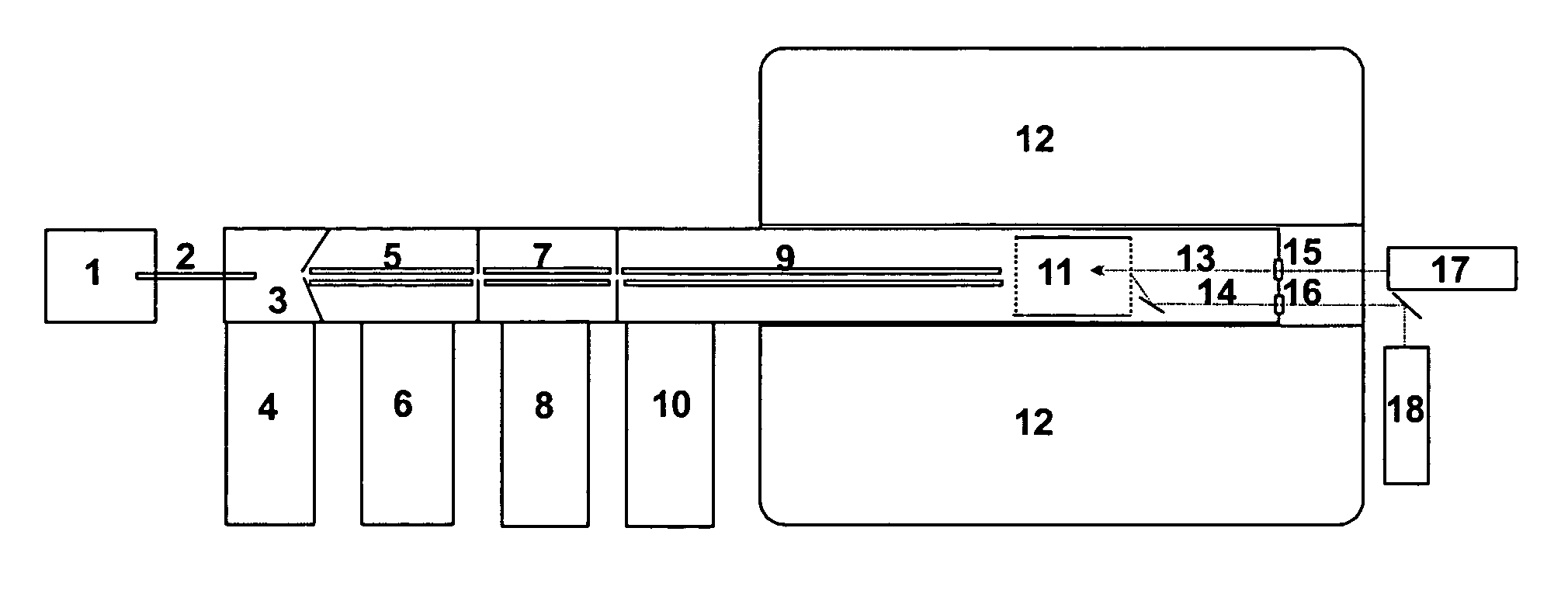
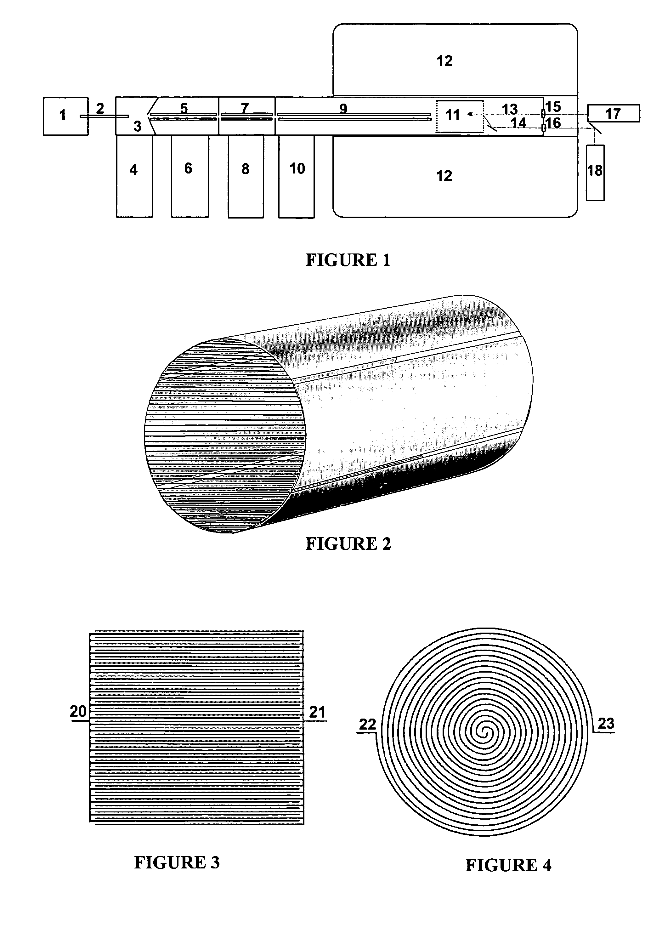
[0028]A preferred embodiment is schematically shown in FIG. 1. Ions generated inside an ion source (1) are fed, together with ambient gas, through a capillary (2) into a first vacuum chamber (3) wherein a large portion of the gas is pumped away by the vacuum pump (4). In further differential pumping stages (5), (7), and (9), each with ion guide systems, more gas is pumped by pumps (6), (8), and (10). The ions enter the ICR trap (11) inside the superconducting magnet system (12) and are trapped by suitable procedures. The ion guide (7) may be used as a quadrupole filter for the selection of ions to be fragmented. The quadrupole filter (7) also may serve as ion storage unit, transferring ion bunches via ion guide (9) to the ICR trap (11). The infrared laser (17) may be used to fragment ions by IRMPD; the infrared photon beam (13) passes the infrared window (15). The UV laser (18) may be used to generate slow electrons by pulsed irradiation of the grid wires by the UV photon beam (14),...


PUM


Abstract

The invention describes an ion cyclotron resonance (ICR) mass spectrometer with an ICR trap, the ICR trap having as trapping electrodes two ion reflecting electrode structures operated by RF voltages without any DC voltage. The usual apertured ion trapping electrodes are replaced by multitudes of structural elements, electrically conducting, and repeating spatially in one or two directions of a surface, neighboring structure elements being connected each to different phases of an RF voltage. In the simplest case a grid of parallel wires can be used. The surface of such structures reflects ions of both polarities, if the mass-to-charge ratio of the ions is higher than a threshold.

Description

FIELD OF THE INVENTION[0001]The invention relates to the design of ion cyclotron resonance (ICR) traps in Fourier transform mass spectrometers (FTMS) wherein the mass-to-charge ratios of ions are measured by their cyclotron frequency in a strong magnetic field.BACKGROUND OF THE INVENTION[0002]In ion cyclotron resonance (ICR) mass spectrometers, the mass-to-charge ratio of ions is measured by the frequency of their cyclotron oscillations in a homogenous magnetic field of high field strength. The magnetic field is usually produced by superconducting magnet coils, offering usable diameters of homogenous field from four to eight inches. Modern ICR mass spectrometers operate at magnetic fields of 7 to 12 Tesla flux density.[0003]The ion cyclotron frequency is measured in ICR traps mounted inside the magnetic field. The ICR trap consists of at least four lengthy outer electrodes parallel to the magnetic field lines. At least two of the electrodes are used to synchronously accelerate the c...

Claims


Application Information

Patent Timeline
Patent Type & Authority Patents(United States)
IPC IPC(8): H01J49/38H01J49/14
CPCH01J49/38
Inventor NIKOLAEV, EVGENIJ
Owner BRUKER DALTONIK GMBH & CO KG
Why Eureka
Try Eureka