Lidded barrel

a lidded barrel and cylindrical technology, applied in cans/barrels/drums, packaging, transportation and packaging, etc., can solve the problems of not being able to completely detach the barrel lid, the barrel is not readily suited for liquid use, and the lid is easily leaking, etc., to achieve simple and efficient, without space loss

Inactive Publication Date: 2006-05-09
MAUSER WERKE GMBH
View PDF52 Cites 10 Cited by
  • Summary
  • Abstract
  • Description
  • Claims
  • Application Information

AI Technical Summary

Benefits of technology

[0030]Other advantages of the lidded barrel according to the invention consist in the fact that it has dimensions that are identical to the greatest extent possible to those of a corresponding plastic L-ring bung barrel or steel bung barrel, and it can thus be handled with the same barrel-gripping tools (parrot's beak). These lidded barrels can also be handled on pallets together with bung barrels without the losses of space due to big-bellied lidded barrels and differing heights that otherwise usually occur. The filling of the lidded barrels...

Problems solved by technology

This type of a lidded barrel was developed by Mauser in 1975 and distributed worldwide under the designation “standard lidded barrel”; it is well-suited for handling solid, particulate or pasty contents, but such a barrel is not readily suited for use with liquids.
In the case of known existing plastic lidded barrels, even when barrels are dropped from heights of about 1.20 m—e.g., fr...

Method used


Image

  • Lidded barrel
  • Lidded barrel
  • Lidded barrel

Examples


Embodiment Construction

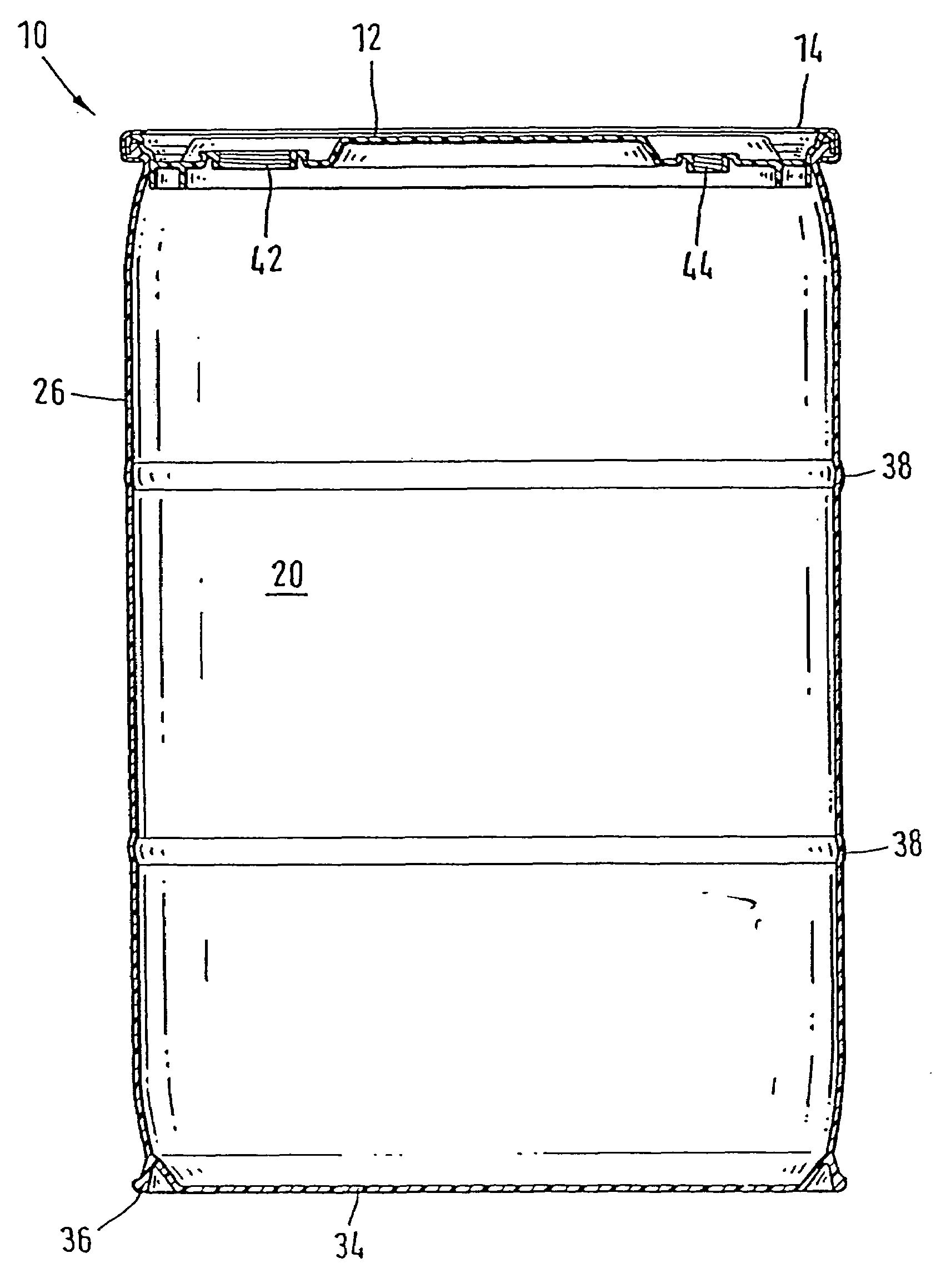
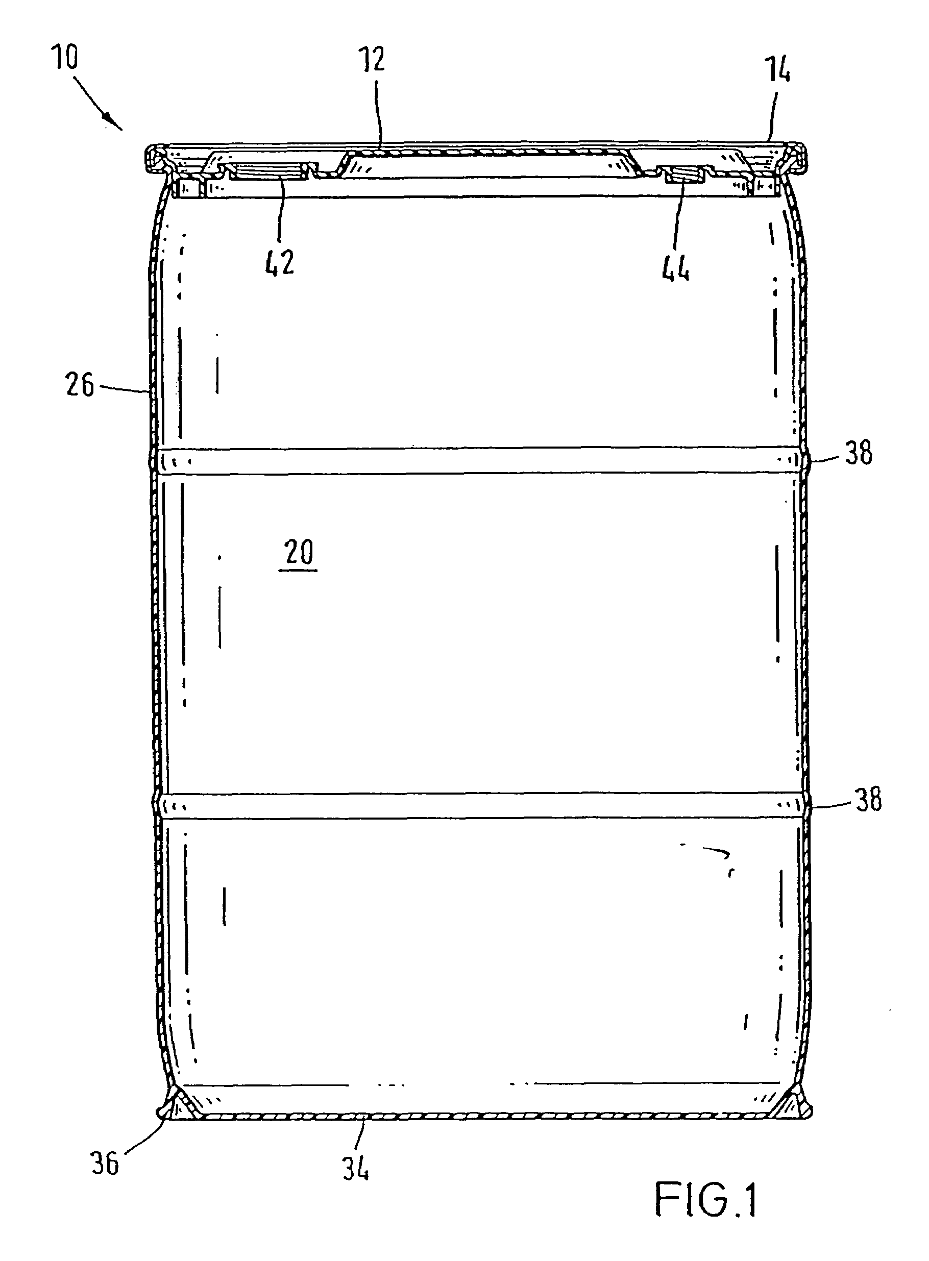
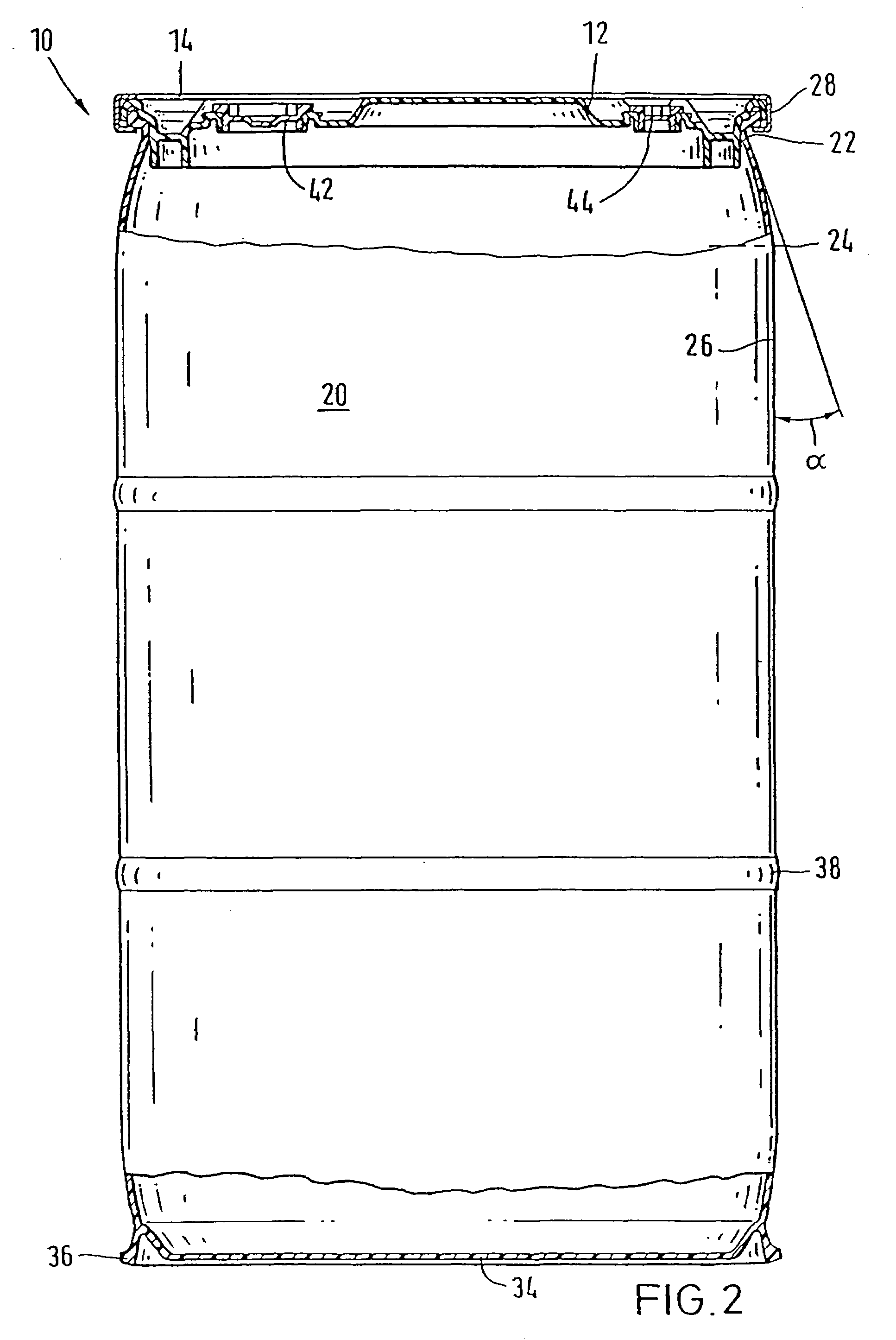
[0048]In FIG. 1, a lidded barrel with a capacity of 55 US gallons here, according to the invention, which is provided with a barrel lid 12 put on and a tension-ring closure 14 in place, is referred to by reference number 10. About 80% of barrel body 20 is designed as fully cylindrical, while about 10% respectively of the barrel height upward toward barrel opening edge 28 and downward toward barrel bottom 34 is drawn in with a slight conical taper. In fully cylindrical part 26 of barrel body 20, two comparatively broad rounded barrel body roller cages 38 are arranged at one-third and two-thirds of the barrel height. In the conically tapered transition area between fully cylindrical part 26 of barrel body 20 and flat barrel bottom 34, a solid bottom roller cage 36 that ends flush with barrel bottom 34 is provided. Bottom roller cage 36 has a trapezoidal cross section below with a thinner bridge connection to barrel body 20 and an outside diameter that is almost identical to that of te...


PUM


Abstract

This invention relates to a cylindrical, blow-molded lidded barrel (wide-mouthed drum) with a barrel lid and tension-ring closure. Previously known lidded barrels have comparatively little ability to withstand falls and are therefore not well-suited for handling liquids. Owing to the special configuration of the barrel lid and the barrel mouth edges as well as by a special matching of the individual components to one another, the lidded barrel according to the invention can be manipulated in the filled state with the same barrel-gripping tool (parrot's beak), ans is universally employed and in industrial use for modern plastic L-ring bung barrels or normal steel bung barrels. By improving the strength of the lidded barrel when it is dropped, the barrel is also made especially well-suited for handling liquids since it remains liquidtight even when dumped or dropped from great heights.

Description

[0001]This is a continuation application of U.S. application Ser. No. 09 / 363,017 filed Jul. 29, 1999, now U.S. Pat. No. 6,116,453, which is a continuation of Ser. No. 08 / 793,751 filed Jun. 11, 1997, now U.S. Pat. No. 5,964,367, which is a 371 of application filed Sep. 12, 1995 as the National Phase of PCT / EP95 / 03586, now U.S. Pat. No. 5,964,367, which is a continuation-in-part of U.S. application Ser. No. 08 / 283,695 filed Aug. 1, 1994, now U.S. Pat. No. 5,593,060, which is a continuation application of U.S. application Ser. No. 08 / 049,722, filed Apr. 20, 1993, now abandoned.BACKGROUND OF THE INVENTION[0002]This invention relates to a cylindrical, blow-molded lidded barrel (wide-mouthed drum) with a barrel lid and tension-ring closure, in which in the closed position, the tension ring, which is U-shaped in cross section, engages with its upper leg over the outside upper edge of the lid and engages with its lower leg under an outside edge of the barrel that runs basically horizontally...

Claims


Application Information

Patent Timeline
IPC IPC(8): B65D1/42
CPCB65D11/06
Inventor PRZYTULLA, DIETMAR
Owner MAUSER WERKE GMBH
Why Eureka
Try Eureka