
Programmable electricity consumption monitoring system and method

a technology of programmable electricity consumption and monitoring system, which is applied in the direction of electric controllers, instruments, analysing/displaying, etc., can solve the problems of reducing power consumption and difficult for the average consumer

Active Publication Date: 2006-05-09
ELMO CORP
View PDF55 Cites 211 Cited by
  • Summary
  • Abstract
  • Description
  • Claims
  • Application Information

AI Technical Summary

Benefits of technology

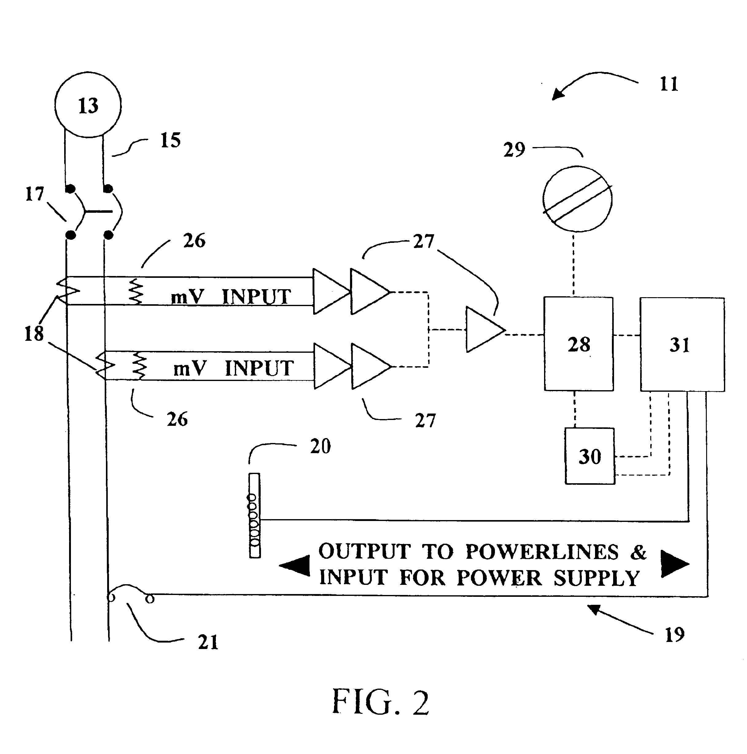
"The present invention is a programmable system for monitoring electricity consumption by a residence or business. It includes a measuring transmitting unit and a receiving display unit. The measuring transmitting unit receives current from the main service power conductors and converts it to digital signals. These signals are then transmitted over existing power lines in the residence or business using power line carrier technology. The receiving display unit receives the transmitted signals, decodes them, and converts them to power measurements. The system can also be connected to load shedding devices for controlling power consumption. The invention allows for easy installation and real-time monitoring of electricity consumption."

Problems solved by technology

Reducing power consumption, though advantageous for the public as a whole as well as the private individual, is difficult for the average consumer.

Method used


Image

  • Programmable electricity consumption monitoring system and method
  • Programmable electricity consumption monitoring system and method
  • Programmable electricity consumption monitoring system and method

Examples


Embodiment Construction

[0040]In the following description, like reference characters designate like or corresponding parts throughout the several views. Also, in the following description, it is to be understood that such terms as “front,”“back,”“within,” and the like are words of convenience and are not to be construed as limiting terms. Referring in more detail to the drawings, the invention will now be described.

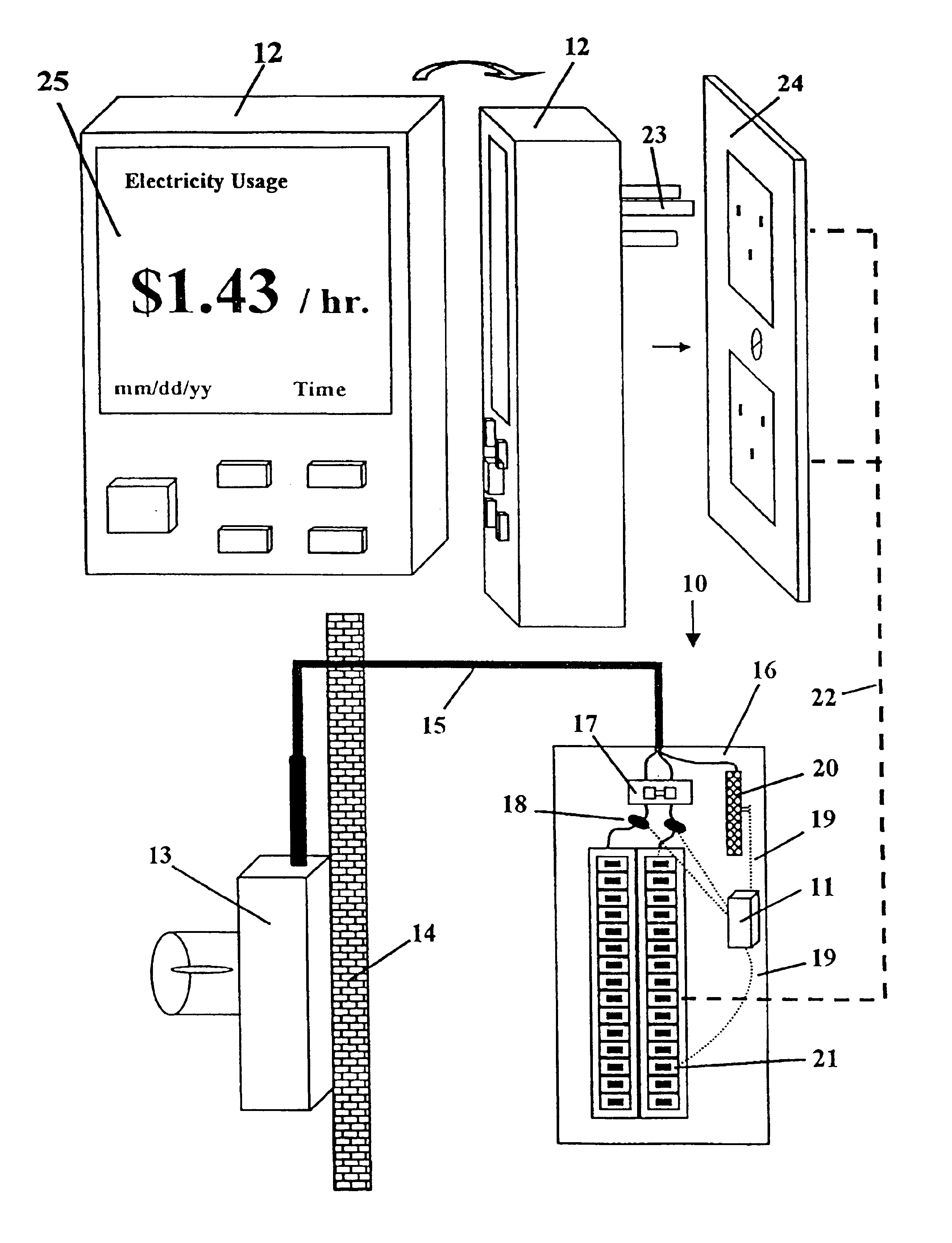
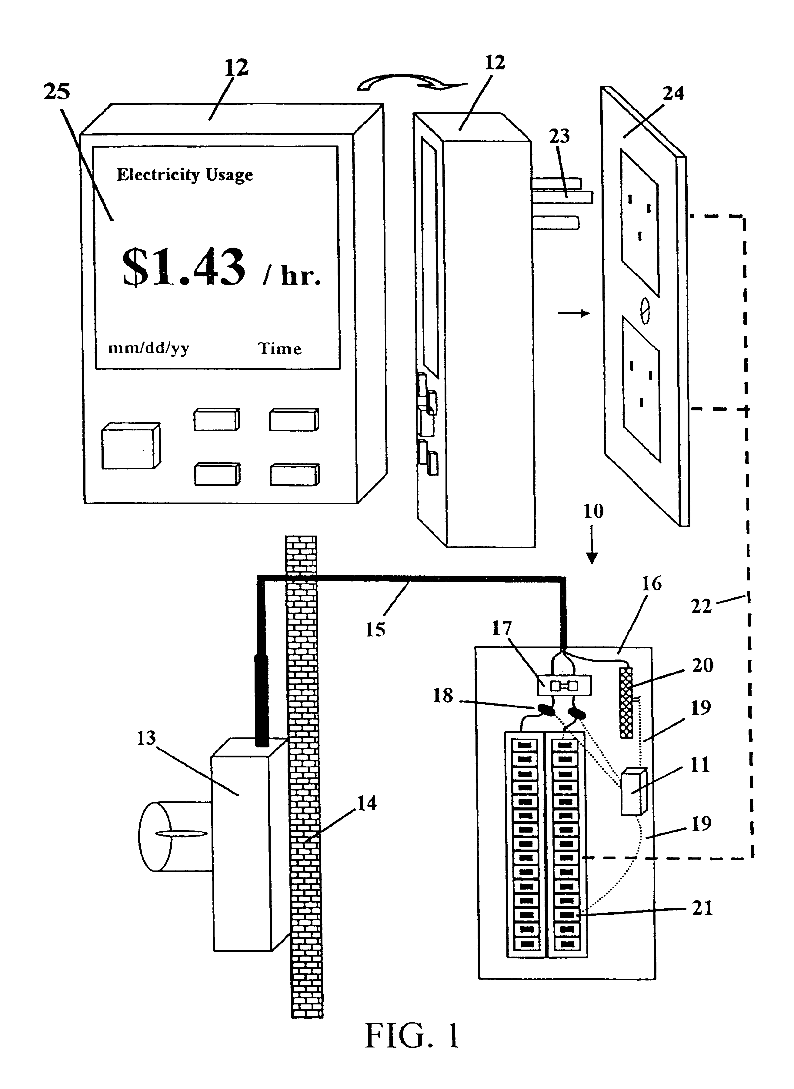
[0041]Referring to FIG. 1, a programmable electricity monitoring system 10 according to the present invention comprises a Measuring Transmitting Unit (MTU) 11 and a Receiving Display Unit (RDU) 12.

[0042]The Measuring Transmitting Unit 11 is shown at the bottom of FIG. 1. On the left of FIG. 1, a utility KWH (kilowatt hour) meter 13 is shown on an exterior wall 14 of a residence or business. KWH meters are usually installed by power companies on the outside of buildings of their customers to measure power consumption by each customer. A main service power circuit 15 extends from the KWH meter 13...


PUM


Abstract

A programmable system for monitoring electricity consumption by a residence or business, including:(a) a Measuring Transmitting Unit integrated in a main circuit breaker or utility meter in the residence or business; comprising: (1) a means of receiving AC analog signals, converting the AC analog signals to DC analog signals, summing the DC analog signals, and outputting the information; (2) a microcontroller; (3) a power line carrier transmission interface controller; and (4) a power supply for powering the Measuring Transmitting Unit; and(b) a programmable Receiving Display Unit, comprising: (1) a power supply for powering the Receiving Display Unit; (2) a power plug; (3) a power line carrier transmission interface controller; (4) a data decoder; (5) a microcontroller; (6) memory associated with the microcontroller; (7) a visual display; and (8) a mechanism for inputting to the Receiving Display Unit; andwherein the Measuring Transmitting Unit translates current to digitally encoded signals, and transmits the signals over existing power circuits in the residence or business; and the Receiving Display Unit receives the signals, decodes them, and translates them for viewing. A method for monitoring electricity consumption by a residence or business is also included.

Description

BACKGROUND OF THE INVENTION[0001]1. Technical Field[0002]The present invention refers to a system and method for monitoring energy usage, preferably a system for continuously measuring and displaying electrical power consumption and cost at a consumer's residence or business.[0003]2. Background Information[0004]Our society recognizes its dependence upon electricity for day to day living, as well as the need to develop alternate forms of energy. Reducing power consumption, though advantageous for the public as a whole as well as the private individual, is difficult for the average consumer. The average consumer only receives feedback regarding power consumption upon receipt of a monthly bill from the power company.[0005]A need exists for a practical, programmable, user friendly, affordable, portable system for continuous, contemporaneous monitoring of power consumption; a system that is integral with a main circuit breaker or utility meter and can easily be installed by a contractor ...

Claims


Application Information

Patent Timeline
Patent Type & Authority Patents(United States)
IPC IPC(8): G01R21/00G01D4/00G01R22/00H02J13/00H04M11/04
CPCG01D4/006G01R22/00Y02B90/243Y04S20/325Y04S20/46Y02B90/245Y04S20/40Y04S20/30G01D2204/18Y02B90/20
Inventor RODENBERG, III, ERNEST ADOLPHBORDEN, ROBERT RICHARD
Owner ELMO CORP
Learn More