Spring loaded and self-locking cable gripping apparatus

a self-locking, cable technology, applied in the direction of snap fasteners, mechanical devices, buckles, etc., can solve the problems of causing confusion for users, and reducing the service life of the devi

Active Publication Date: 2006-05-16
FEENEY WIRE ROPE & RIGGING
View PDF10 Cites 26 Cited by
  • Summary
  • Abstract
  • Description
  • Claims
  • Application Information

AI Technical Summary

Benefits of technology

[0007]The embodiments of the present invention solve the problems and address the drawbacks of the approaches in the above description. It is an object of the present invention to provide a spring loaded and self-locking cable gripping apparatus of a minimum of components, sturdy, non-corrosive, and capable of securing a variety of cable materials of even very small diameter. It is an object of the present invention to provide a finished look to a cable apparatus in use and at the same time protect the. components of the apparatus from damage.
[0010]In the preferred embodiment, the apparatus comprises an end cap at the dispatching end of the housing including an o-ring for sealing the dispatching end of the housing from the environment and providing a clean finish. When in use, the gripping apparatus is enclosed in a structure and only the end cap remains visible on the structure.

Problems solved by technology

However, such devices often have too many components.
The multiplicity of components create confusion for the user.
Further, such components are prone to be lost, misplaced or damaged, rendering the device useless.
Such devices are also larger than necessary, requiring additional material to manufacture.
Also, components of such devices are shaped in complicated designs for instance T-shaped cutouts, requiring added expense when manufacturing the components as well as increasing the possibility that components will not fit well.
Additionally, with prior devices, dirt and moisture are prone to becoming trapped within such devices.
This often leads to corrosion of the cables held within the devices.
Furthermore, there are no devices to accommodate smaller sized cables with diameters such as small as 1 / 16 inch to ⅛ inch.

Method used


Image

  • Spring loaded and self-locking cable gripping apparatus
  • Spring loaded and self-locking cable gripping apparatus
  • Spring loaded and self-locking cable gripping apparatus

Examples


Embodiment Construction

[0021]The description above and below and the drawings of the present document focus on one or more currently preferred embodiments of the present invention and also describe some exemplary optional features and / or alternative embodiments. The description and drawings are for the purpose of illustration and not limitation. Those of ordinary skill in the art would recognize variations, modifications, and alternatives. Such variations, modifications, and alternatives are also within the scope of the present invention.

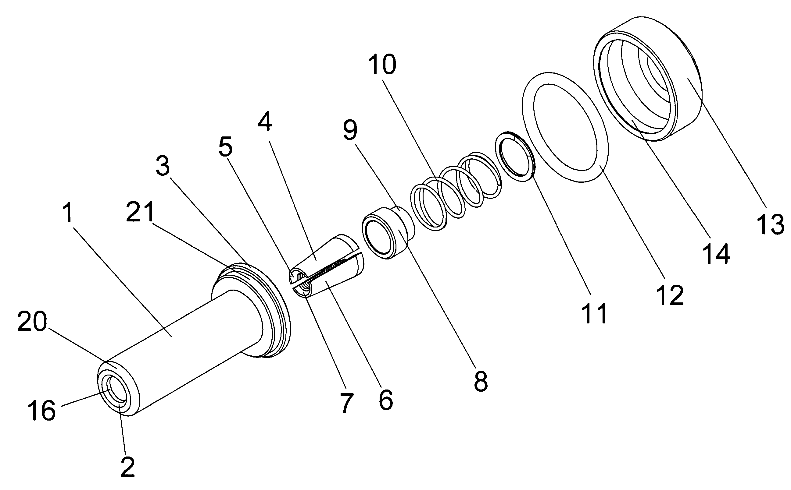
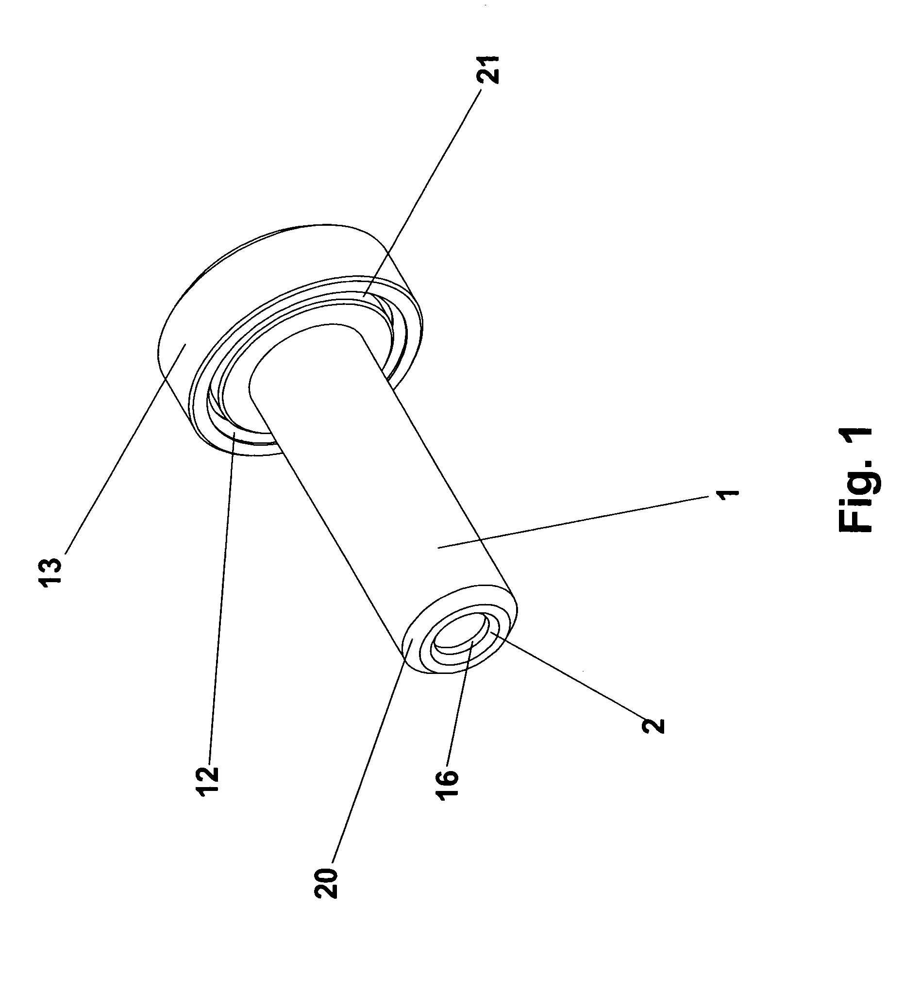
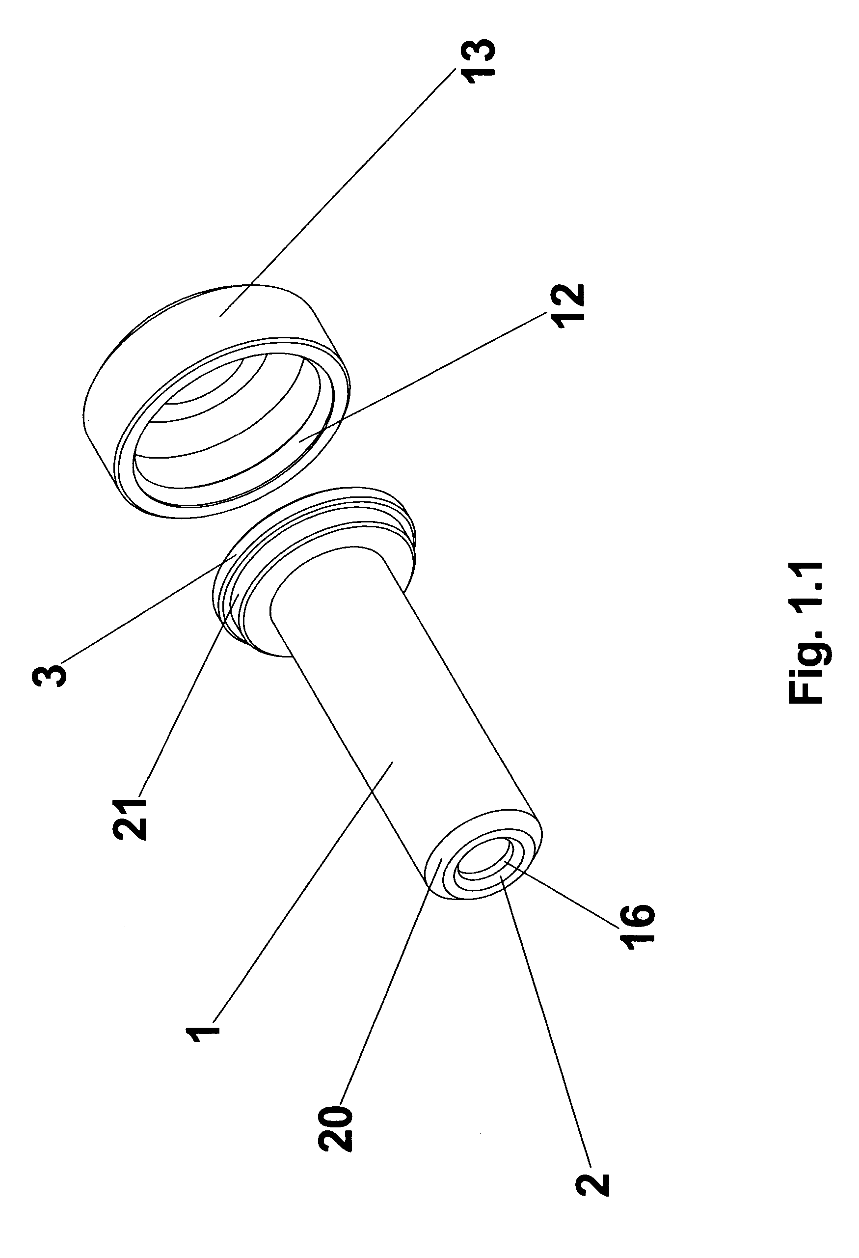
[0022]FIG. 1 shows a perspective view of an embodiment of the spring loaded and self-locking cable gripping apparatus in its fully assembled state. The apparatus comprises a cylindrical main housing 1 having a central passageway beginning from the bore 16 and a cap 13. In the preferred embodiment, the main housing 1 further comprises an inside bevel 2 located on a first end side, an outside bevel 20, a large diameter outside flange 21 located on a second end side of the m...


PUM


Abstract

An embodiment of the present invention is a cable gripping apparatus comprised of a housing with a part conical shaped passageway, two serrated half-jaws, a spacer, a spring, a retaining clip and a cap. The apparatus is spring-loaded and self-locking for gripping and securing a cable. The serrated half-jaws and spring lock the cable in place and only allows the cable to move in one direction. The cap is placed at one end of the apparatus to prevent dirt and moisture from accumulating, thus minimizing the corrosion of the cable.

Description

CROSS REFERENCE[0001]This application claims the benefit of priority from U.S. Provisional Application No. 60 / 508,254 entitled “Spring Loaded and Self-Locking Cable Gripping Apparatus”, filed Oct. 3, 2003, which is herein incorporated by reference.FIELD OF INVENTION[0002]The present invention generally relates to an improved cable gripping apparatus which allows a user to secure a variety of cable materials, make adjustments to the length and tension of the cable materials, and shield the cable materials in a stainless steel casing to minimize corrosion of said cable materials.BACKGROUND OF THE INVENTION[0003]There exists in the field of securing cables, devices for gripping and anchoring a variety of cables to enclosures or structures. The conventional procedure for cable gripping devices involves a casing with a hollow conical-shaped wedge, wherein the wedge contains a threaded inner surface. Some devices additionally provide a spring held within the one end of the conical-shaped ...

Claims


Application Information

Patent Timeline
Patent Type & Authority Patents(United States)
IPC IPC(8): F16G11/00F16G1/04
CPCF16G11/04Y10T24/3969F16G11/106
Inventor TOIMIL, ANDREW G.
Owner FEENEY WIRE ROPE & RIGGING
Why Eureka
Try Eureka