Inverter for a distributed power generator

a technology of distributed power generators and inverters, which is applied in the direction of dc-ac conversion without reversal, process and machine control, instruments, etc., can solve the problem of limiting the life of the circui

Active Publication Date: 2014-03-11
SPARQ SYST INC
View PDF35 Cites 17 Cited by
  • Summary
  • Abstract
  • Description
  • Claims
  • Application Information

AI Technical Summary

Benefits of technology

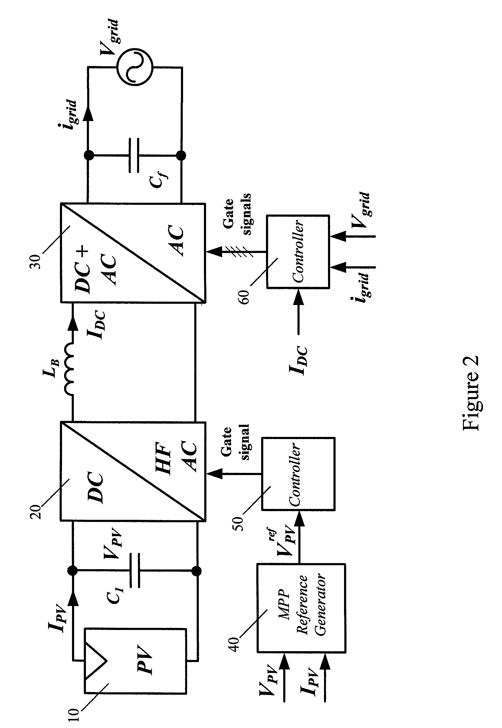
[0008]Described herein is a maximum power point (MPP) tracker topology which decouples output power oscillations from the PV cell power generation. The topology may extract the maximum available power from each PV cell string of a multi-string system independently. The circuit uses a minimum number of components and avoids the use of large electrolytic capacitors, which is a major factor in limiting circuit life time. The MPP tracker is not limited to low-power applications. Such decoupling, described herein, is applicable to voltage source converter topologies and current source converter topologies.
[0011]Also described herein is a PV cell inverter using a current source (e.g., buck-boost) topology in which the output voltage may be greater or smaller than the voltage of the input PV cell. Unlike voltage source topologies, the inverter directly generates and feeds the desired current into the grid using a modified pulse width modulation (PWM) technique. The modified PWM technique and control strategy optimize the middle stage dc current level in the inverter. This results in a flatter efficiency curve for a wide range of input power. The PV cell may comprise a string of multiple PV cells, or multiple strings of PV cells.
[0022]The topologies described herein accept low PV cell voltages at the input, which increases efficiency in partial shading conditions, compared to topologies in which many PV cells are connected in series to build up a high input voltage.

Problems solved by technology

The circuit uses a minimum number of components and avoids the use of large electrolytic capacitors, which is a major factor in limiting circuit life time.

Method used


Image

  • Inverter for a distributed power generator
  • Inverter for a distributed power generator
  • Inverter for a distributed power generator

Examples


example

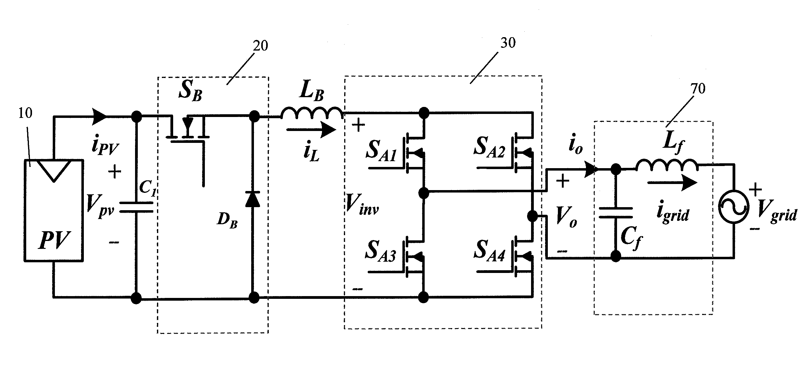
[0100]To demonstrate the impact of the irradiance level, input voltage level, and partial shading on the performance of a two-string PV cell inverter as shown in FIGS. 5B and 8, a simulation was carried out using PSIM 7.0 software and the values set forth in Table I, and the results are shown in FIG. 10. The system was started with string #2 partially shaded (40% of the full irradiation level) and string #1 at full power. At t=0.2 (s) both strings were partially shaded at 15% of the full irradiation level and the system response was obtained. At t=0.3 (s) the temperature of the PV cells was increased so that the output voltage of the PV cells decreased from 150V to 80V, which is less than the grid voltage. At t=0.4 (s) both strings were exposed to full irradiance. It can be seen from FIG. 10 that after each change, the controller quickly stabilized the output current. In addition, the maximum input power extraction was almost instantaneous, confirming the fast dynamic response of th...


PUM


Abstract

Provided is a maximum power point (MPP) tracker for a PV cell inverter, and a PV cell inverter. The MPP tracker decouples output power oscillations from the input power generation and extracts maximum available power from the PV cell. The PV cell inverter uses the MPP tracker and generates a sinusoidal output current from the MPP tracker output. The sinusoidal output current may be fed to a power distribution grid. The PV cell inverter may use a pulse width modulation technique to cancel harmonics in the sinusoidal output current. The circuits use a minimum number of components and avoid use of large electrolytic capacitors.

Description

RELATED APPLICATIONS[0001]This application claims the benefit of the filing date of U.S. Provisional Patent Application No. 61 / 202,355, filed on Feb. 20, 2009, the contents of which are incorporated herein by reference in their entirety.FIELD OF THE INVENTION[0002]This invention relates to circuits, systems, and methods for obtaining power from a distributed power generator such as a photovoltaic cell, and for interfacing a distributed power generator to a power distribution grid. In particular, this invention relates to a maximum power point tracker and a string / multi-string photovoltaic cell inverter incorporating the maximum power point tracker.BACKGROUND OF THE INVENTION[0003]Grid-connected distributed power generators such as photovoltaic (PV) systems typically consist of two major parts: PV cell arrays to convert irradiation to electrical energy, and an inverter to feed the electrical energy into a power distribution grid. PV cell configurations may be categorized according to...

Claims


Application Information

Patent Timeline
Patent Type & Authority Patents(United States)
IPC IPC(8): H02M1/14H02M7/515H02J5/00H02S40/32
CPCH01L31/02021H02M1/14Y02E10/58H02M7/48H02M1/12G05F1/67H02J3/383Y02E10/563H02J2300/24H02J3/381Y02E10/56
Inventor KHAJEHODDIN, SAYED ALIJAIN, PRAVEENBAKHSHAI, ALIREZA
Owner SPARQ SYST INC
Why Eureka
Try Eureka