Tank venting device for a fuel tank of a motor vehicle

a technology for venting devices and fuel tanks, which is applied in the direction of machines/engines, combustion air/fuel air treatment, transportation and packaging, etc., can solve the problem that activated carbon filters possibly charged with a greater amount of hydrocarbons cannot be regenerated over a long period

Inactive Publication Date: 2012-05-10
AUDI AG
View PDF12 Cites 22 Cited by
  • Summary
  • Abstract
  • Description
  • Claims
  • Application Information

AI Technical Summary

Benefits of technology

[0008]In accordance with the present invention, a tank venting device is realized which has a minimum of components and can easily be operated by using a single controllable solenoid valve which permits to simultaneously clear the gas flow through the first and second gas lines in the event both gas lines have to be opened, for example during refueling of the motor vehicle so as to route the gas flow, displaced from the fuel tank and charged with hydrocarbons, through the activated carbon filter for purging the hydrocarbons.
[0013]According to another advantageous feature of the present invention, at least two overflow valves can be switched in parallel, with one of the overflow valves constructed in the form of an overpressure protection valve and with the other one of the overflow valves constructed in the form of a low pressure protection valve. In this way, unwanted overpressure or low pressure in the fuel tank as a result of a severe temperature rise of temperature drop, respectively, can be prevented. The terms “overpressure” and “low pressure” relate hereby to atmospheric pressure. Thus, one of the overflow protection valves opens, when the pressure in the fuel tank exceeds an upper threshold value above atmospheric pressure, whereas the other one of the overflow protection valves opens, when the pressure in the fuel tank falls below a lower threshold value below atmospheric pressure. In this way, pressure compensation is attained in both cases by the first gas line, activated carbon filter, and second gas line, even when the solenoid valve is closed.

Problems solved by technology

Thus, in these types of motor vehicles, an activated carbon filter possibly charged with a greater amount of hydrocarbons may not be regenerated over a lengthy period.

Method used


Image

  • Tank venting device for a fuel tank of a motor vehicle
  • Tank venting device for a fuel tank of a motor vehicle
  • Tank venting device for a fuel tank of a motor vehicle

Examples


first embodiment

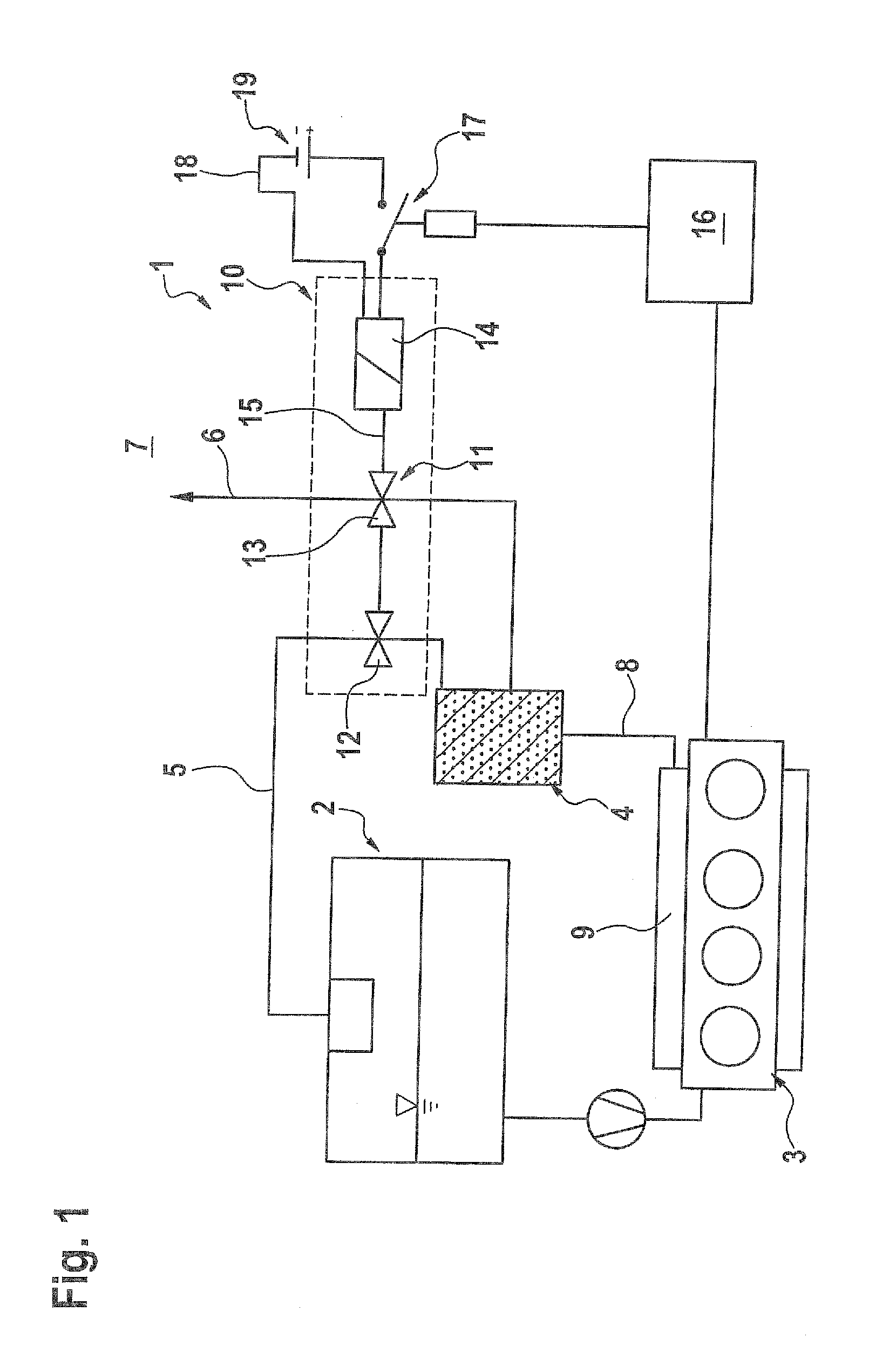
[0022]Turning now to the drawing, and in particular to FIG. 1, there is shown a schematic illustration of a tank venting device according to the present invention, generally designated by reference numeral 1, for venting a fuel tank 2 of a plug-in electric drive motor vehicle (not shown) which is operated by an electric motor (not shown) and includes an internal combustion engine 3 as auxiliary motor for charging a vehicle battery 19.

[0023]The tank venting device 1 includes an activated carbon filter 4. A first gas line 5 connects the activated carbon filter 4 with the interior of the fuel tank 2. A second gas line 6 connects the activated carbon filter 4 with the environment or atmosphere 7, and a third gas line 8 connects the activated carbon filter 4 with an intake tract 9 of the internal combustion engine 3. The tank venting device 1 further includes a valve unit 10 which is indicated in FIG. 1 by a broken line. The valve unit 10 includes a two-stage solenoid valve 11 which has ...

second embodiment

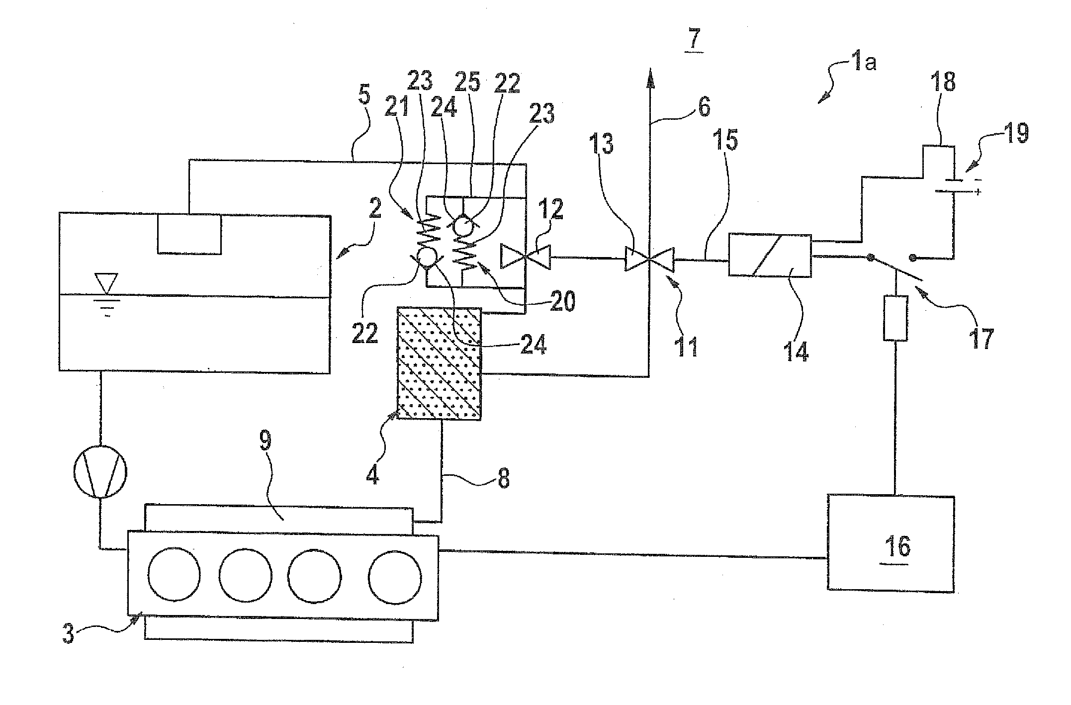
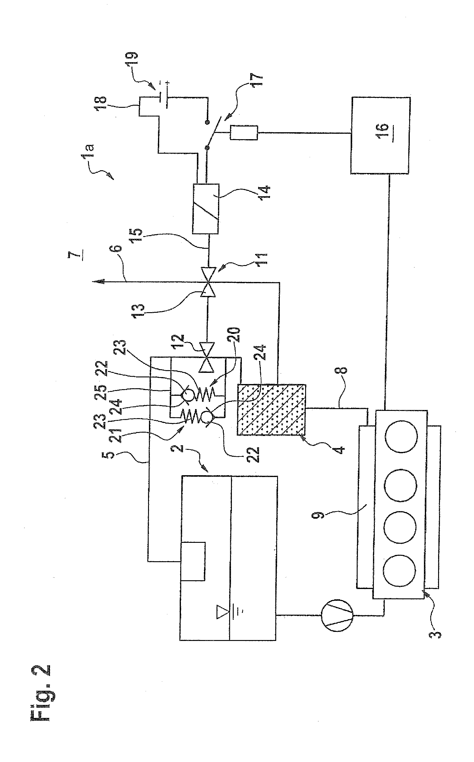
[0027]Referring now to FIG. 2, there is shown a schematic illustration of a tank venting device according to the present invention, generally designated by reference numeral 1a. Parts corresponding with those in FIG. 1 are denoted by identical reference numerals and not explained again. The description below will center on the differences between the embodiments. In this embodiment, provision is made for the presence of at least two overflow valves 20, 21. Each of the overflow valves 20, 21 includes a valve member 22 which is urged by a valve spring 23 against a valve seat 24. The overflow valve 20 operates hereby as overpressure protection valve whereas the overflow valve 21 operates as low pressure protection valve. The overpressure protection valve 21 opens spontaneously, when the pressure on the valve-spring-distal side of the valve member 22 exceeds an opening pressure defined by the spring force, and closes spontaneously, when the pressure drops again below the opening pressur...

third embodiment

[0029]FIG. 3 shows a schematic illustration of a tank venting device according to the present invention, generally designated by reference numeral 1b. Parts corresponding with those in FIGS. 1 and 2 are denoted by identical reference numerals and not explained again. The description below will again center on the differences between the embodiments. In this embodiment, provision is made for two pairs of overflow valves 20, 21 and 20b, 21b.

[0030]In general, overflow valves are always arranged in pairs, with one overflow valve of each pair operating as overpressure protection valve and the other overflow valve of each pair operating as low pressure protection valve.

[0031]In the tank venting device 1b of FIG. 3, the pair of overflow valves 20, 21 is arranged in a same manner as described with reference to the tank venting device 1a of FIG. 2, with a bypass line 26 which branches off the first gas line 5 upstream of the first valve stage 12 and feeds back into the first gas line 5 down...


PUM


Abstract

A tank venting device for a fuel tank of a motor vehicle includes an activated carbon filter which is connected to a fuel tank via a first gas line and connected to the atmosphere or ambient environment via a second gas line. A valve unit includes a single two-stage solenoid valve to control a gas flow through the first and second gas lines.

Description

CROSS-REFERENCES TO RELATED APPLICATIONS[0001]This application claims the priority of German Patent Application, Serial No. 10 2010 019 831.5, filed May 8, 2010, pursuant to 35 U.S.C. 119(a)-(d), the content of which is incorporated herein by reference in its entirety as if fully set forth herein.BACKGROUND OF THE INVENTION[0002]The present invention relates to a tank venting device for a fuel tank of a motor vehicle.[0003]The following discussion of related art is provided to assist the reader in understanding the advantages of the invention, and is not to be construed as an admission that this related art is prior art to this invention.[0004]A fuel tank for a motor vehicle is usually provided with a tank venting device to prevent a buildup of an unwanted overpressure or unwanted low pressure inside the fuel tank when the ambient temperature rises or drops excessively as a result of condensation of fuel caused by a temperature rise or condensation of fuel vapors caused by a tempera...

Claims


Application Information

Patent Timeline
Patent Type & Authority Applications(United States)
IPC IPC(8): F02M33/02F02M33/04
CPCB60K15/03504B60K15/03519B60K2015/03302F02M25/0836F02M25/08
Inventor HAGEN, HARALD
Owner AUDI AG
Why Eureka
Try Eureka