
Cutting mechanism minute adjustment device for a stone cutter

a stone cutter and cutting mechanism technology, applied in metal sawing devices, manufacturing tools, working accessories, etc., can solve the problems of inconvenient operation, blades that are not exactly perpendicular to the surface, and the cutting mechanism of a portable stone cutter cannot perform minute adjustment, so as to achieve convenient operation

Inactive Publication Date: 2006-05-16
TSAO WEN HAI
View PDF5 Cites 1 Cited by
  • Summary
  • Abstract
  • Description
  • Claims
  • Application Information

AI Technical Summary

Benefits of technology

"The present invention is a cutting mechanism adjustment device for a stone cutter. The device allows for horizontal and vertical adjustments of the cutting mechanism, as well as calibration of the blade. The adjustment and calibration process is convenient and easy. The device includes a framed base, a hollow interior support arm, a sustaining plate, and an adjustable plate. The adjustable plate has a pair of adjustable slots and a rectangular hole for permitting the support arm passing through. The adjustment is very rapid and convenient. Overall, the invention provides a cutting mechanism adjustment device that allows for precise and easy adjustments."

Problems solved by technology

However, this type of stone cutter, after repeated assembly and disassembly will be structurally deformed to cause that the blade does not exactly perpendicular to the surface of a stone.
But the balancement of the cutting mechanism is the most important cause.
If the cutting mechanism is not at a correct position the blade is not easily adjusted or calibrated.
The cutting mechanism in a conventional portable stone cutter could only permit to conduct vertical adjustment and could not perform minute adjustment.

Method used


Image

  • Cutting mechanism minute adjustment device for a stone cutter
  • Cutting mechanism minute adjustment device for a stone cutter
  • Cutting mechanism minute adjustment device for a stone cutter

Examples


Embodiment Construction

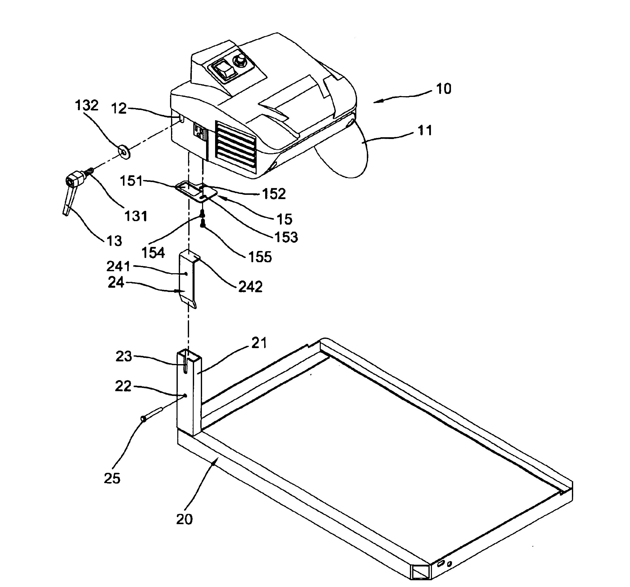
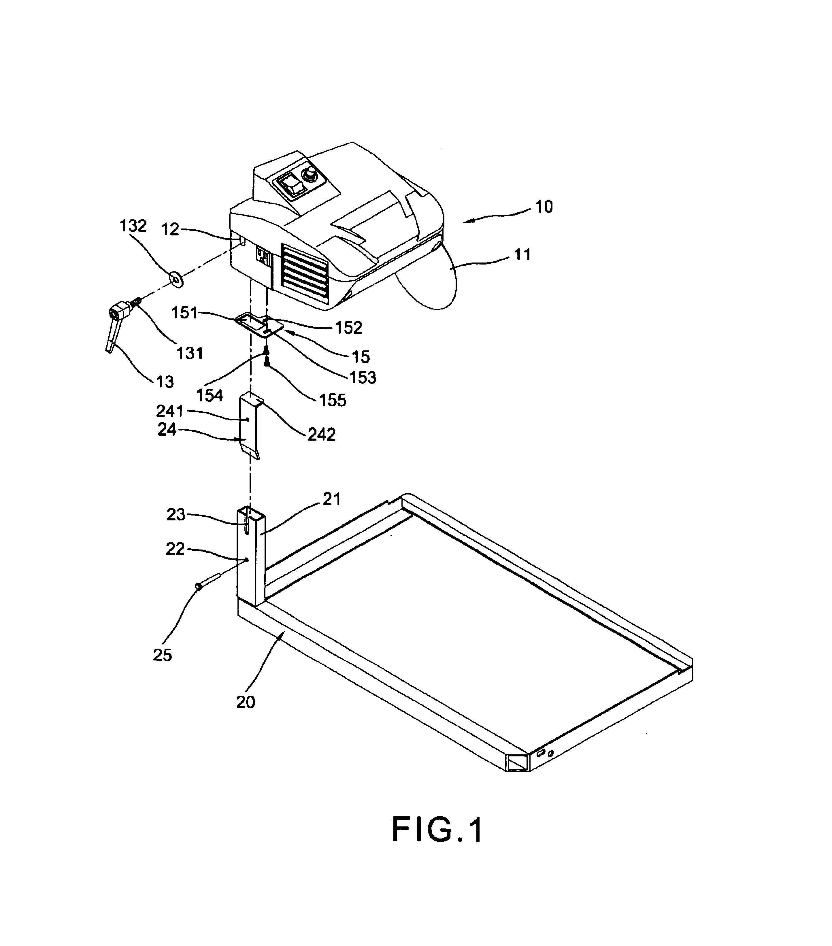
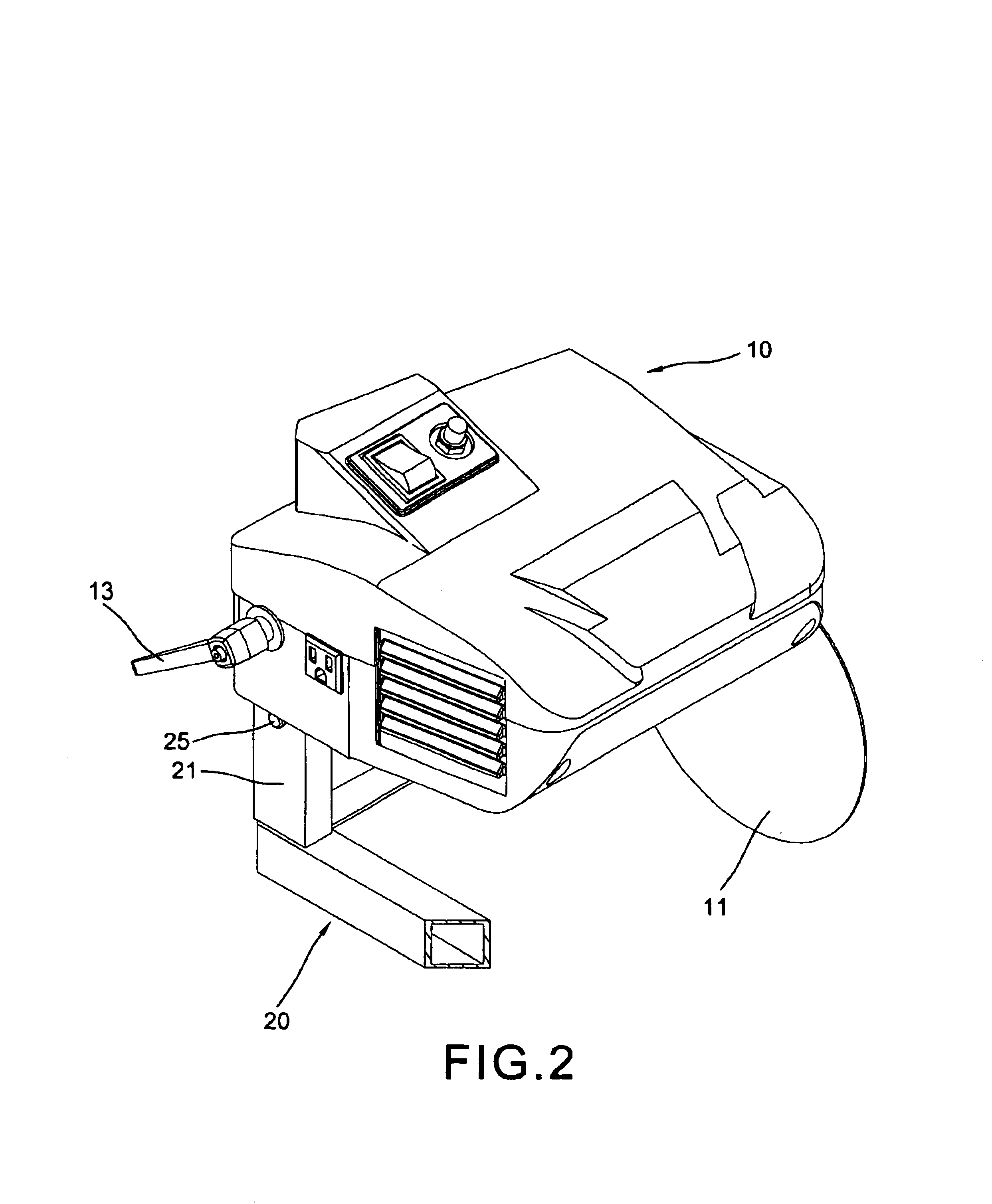
[0015]With reference to FIGS. 1, 2 and 3 of the drawings, the cutting mechanism minute adjustment device for a stone cutter of the present invention comprises a cutting mechanism 10 and a framed base 20.

[0016]The cutting mechanism has a circular blade 11 on a right side connected to an axis of a motor inside the mechanism (not shown), a screw hole 12 in a left side thereof communicating to a rectangular receiving space 14 in an underside.

[0017]A hollow interior rectangular support arm 21 projects upward from a front left corner of the base 20 and inserts into the rectangular receiving space 14 of the cutting mechanism 10 (as shown in FIGS. 3 and 5). The hollow interior rectangular support arm 21 has a U-shaped slit 23 in the top of an outer side wall engageable with the screw hole 12 of the cutting mechanism 10 and a screw hole 22 in a middle portion of the same wall. A sustaining plate 24 inserts into the support arm 21 having a transverse portion 242 on the top and a screw hole 24...


PUM

PropertyMeasurementUnit
angleaaaaaaaaaa
slant angleaaaaaaaaaa

Abstract

A cutting mechanism minute adjustment device for a stone cutter includes a framed base having a hollow interior rectangular support arm on a front corner including a sustaining plate fixed therein inserted into a rectangular receiving spaced under a left portion of a cutting mechanism with a L-shaped adjustable plate engaged therebetween. The adjustable plate has a rectangular through holes for passing through the support arm and a pair of adjustable slots engaged with a pair of screw holes under the cutting mechanism and releasably secured by a pair screws. The cutting mechanism further has a circular blade on a right side actuated by a motor therein and a screw hole in a left wall communicating to the rectangular space and a U-shaped slit in a top of the support arm. A lock has a threaded shank on front engaged into the screw hole and the receiving space of the cutting mechanism through the U-shaped slit of the support arm.

Description

BACKGROUND OF THE INVENTION[0001]The present invention relates to stone cutter and more particularly to a cutting mechanism minute adjustment device for stone cutter.[0002]A portable stone cutter is of a separate structure which may be easily assembled to provide convenience to the users. However, this type of stone cutter, after repeated assembly and disassembly will be structurally deformed to cause that the blade does not exactly perpendicular to the surface of a stone. Although the blade is adjustable. But the balancement of the cutting mechanism is the most important cause. If the cutting mechanism is not at a correct position the blade is not easily adjusted or calibrated. The cutting mechanism in a conventional portable stone cutter could only permit to conduct vertical adjustment and could not perform minute adjustment.SUMMARY OF THE PRESENT INVENTION[0003]The present invention has a main object is to provide a cutting mechanism adjustment device for a stone cutter in which ...

Claims


Application Information

Patent Timeline
Patent Type & Authority Patents(United States)
IPC IPC(8): B28D1/04
CPCB28D1/04B23D47/02
Inventor TSAO, WEN-HAI
Owner TSAO WEN HAI
Learn More