Exhaust and/or condensate port for cured in place liners and installation methods and apparatus

a technology of exhaust and/or condensate port and installation method, which is applied in the direction of shaft equipment, hollow wall articles, other domestic objects, etc., can solve the problems of near the pipe joint, and the deterioration of the pipe itsel

Active Publication Date: 2011-12-27
INA ACQUISITION
View PDF9 Cites 1 Cited by
  • Summary
  • Abstract
  • Description
  • Claims
  • Application Information

AI Technical Summary

Benefits of technology

[0028]In each case, once the liner is inflated and bulkhead fitting is in place, the inverting air remains isolated in the liner and / or inflation bladder. A closed valve assembly is attached to the bulkhead fitting with a closure fitting or external threads for attaching a cutting device. The valve is open to permit the cutting device to pierce the cured in place layers, then removed to allow the valve to be closed and the cutting device withdrawn from the bulkhead fitting assembly. Finally, an exhaust hose is attached, the valve opened so that control of exhaust is conveniently done at a remote location. It is a significant aspect of the invention to cure with flow through steam without deflating the liner. This avoids the potential that a loose section of existing pipe will be dislodged and randomly secured in place between the liner and host pipe on reinflation.
[0032]A further object of the invention is to provide an improved method for pull in and inflate installation of a cured in place liner by utilizing flow-through steam to cure the resin.
[0034]Still another object of the invention is to provide an improved method of installation of a cured in place liner wherein air is used to inflate the liner and flow-through steam is used to cure the resin.

Problems solved by technology

It is generally well known that conduits or pipelines, particularly underground pipes, such as sanitary sewer pipes, storm sewer pipes, water lines and gas lines that are employed for conducting fluids frequently require repair due to fluid leakage or deterioration.
The leakage may be due to improper installation of the original pipe, or deterioration of the pipe itself due to normal aging or to the effects of conveying corrosive or abrasive material.
Cracks at or near pipe joints may be due to environmental conditions such as earthquakes or the movement of large vehicles on the overhead surface or similar natural or man made vibrations, or other such causes.
Regardless of the cause, such leakage is undesirable and may result in waste of the fluid being conveyed within the pipeline, or result in damage to the surrounding environment and possible creation of a dangerous public health hazard.
If the leakage continues it can lead to structural failure of the existing conduit due to loss of soil and side support of the conduit.
Because of ever increasing labor, energy and machinery costs, it is increasingly more difficult and less economical to repair underground pipes or portions that may be leaking by digging up and replacing the pipes.
The major disadvantage to the use of these apparatuses with water is the quantity and availability of the inverting water.
There is limit on how much pressure can be used to invert a liner without adversely affecting the quality of the installed CIPP liner and / or damaging to the existing conduit.
This in turn causes an increase on the friction between the inverting CIPP liner and gland.
Moreover, use of a receiving canister disclosed in these patents is not always suitable for medium and large diameter liners.
While the existing methods utilizing hot water to cure have various advantages noted above, the shortcomings tend to increase energy and labor costs as well as involving a significant use of water that may have styrene entrained due to the type of resins typically used.

Method used


Image

  • Exhaust and/or condensate port for cured in place liners and installation methods and apparatus
  • Exhaust and/or condensate port for cured in place liners and installation methods and apparatus
  • Exhaust and/or condensate port for cured in place liners and installation methods and apparatus

Examples


Embodiment Construction

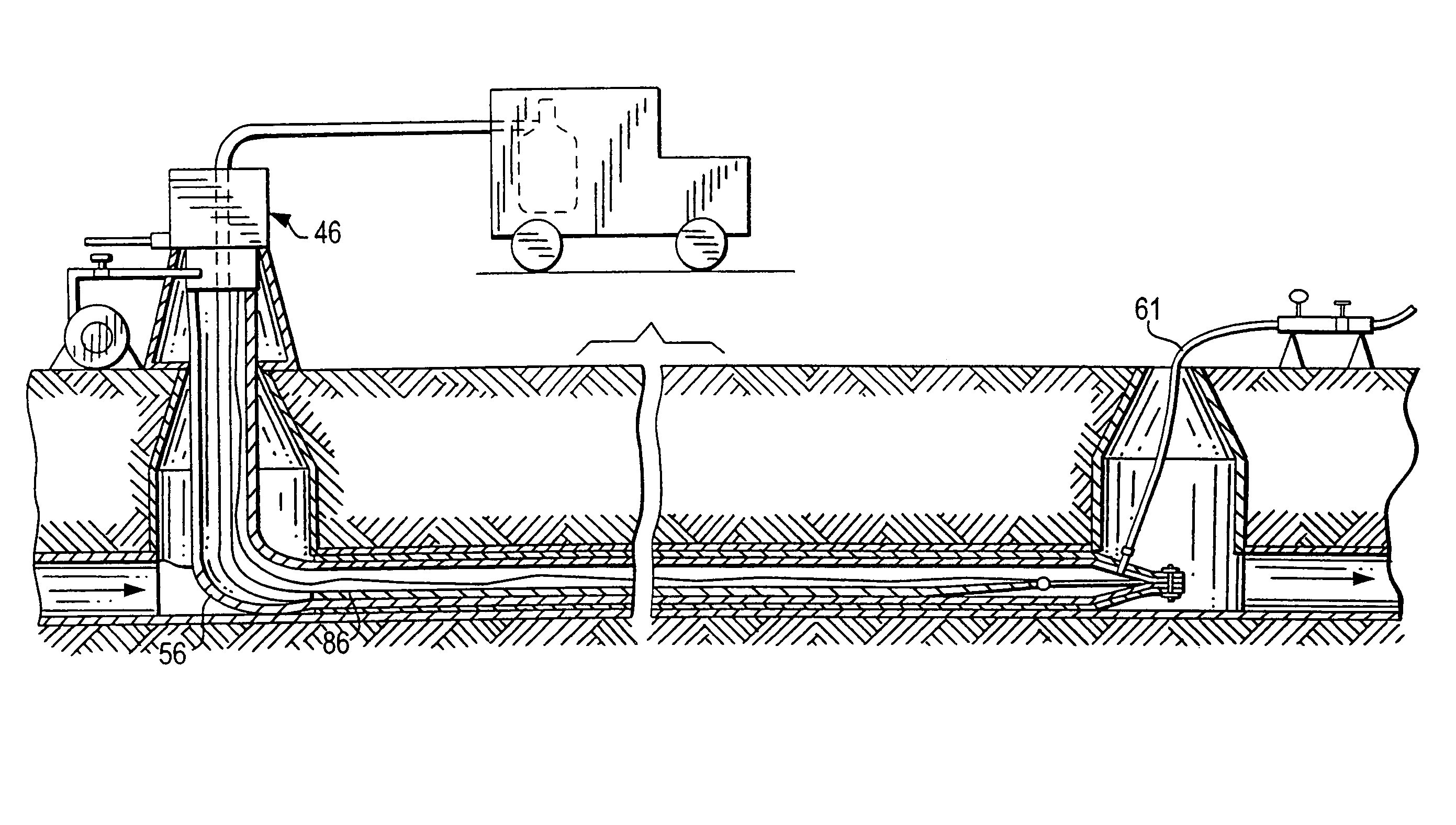
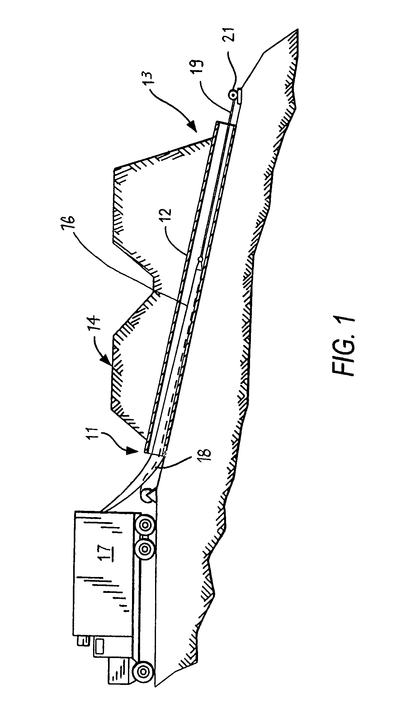
[0054]FIG. 1 shows an upper end 11 of a typical highway culvert crossing 12 passing under a roadway with a lower end 13. A resin impregnated liner 16 is pulled in from the upper end by a winch at the lower end. Liner 16 stored in a refrigerated vehicle 17 is wrapped with a polypropylene sleeve 18 to prevent damage and control longitudinal stretch during pull-in from upper end 11 to lower end 13 by a rope 19 pulled by a winch 21 at lower end 13.

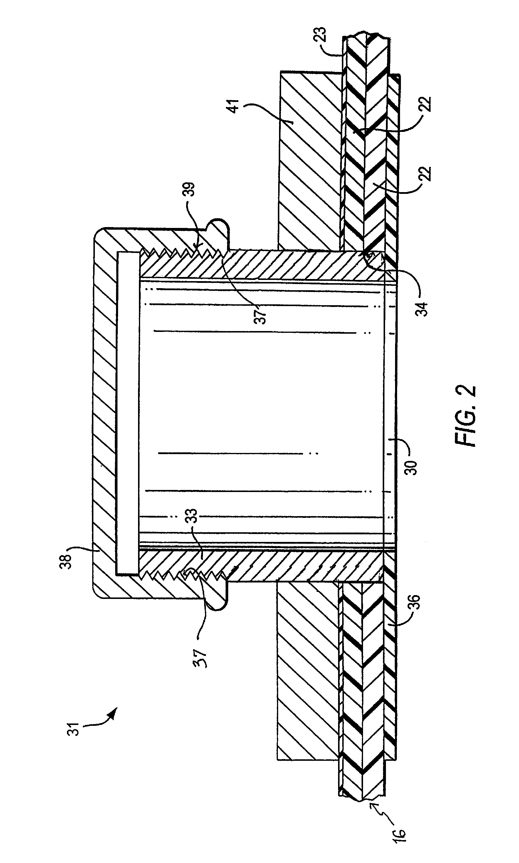
[0055]Liner 16 is a flexible cured in place liner is of the type generally well known in the art. It is formed from at least one layer of a flexible resin impregnable material 22, such as a felt layer having an outer impermeable polymer film layer 23. Felt layers 22 and film layer 23 are stitched along a seam line to form a tubular liner. A compatible thermoplastic film in a form of a tape or extruded material is placed on or extruded over the seam line in order to ensure the impermeability of the liner.

[0056]For larger liner diameters, severa...


PUM

PropertyMeasurementUnit
diameteraaaaaaaaaa
diameteraaaaaaaaaa
diameteraaaaaaaaaa

Abstract

A process for porting air inflated flexible resin impregnated cured in place liner by pulling without loss of pressure is provided. A selectively openable bulkhead fitting is installed at the pull-in end. The filling may be installed in the end of a pull-in liner; on a porting sleeve or secured to an inflated pulled in or inverted liner. A port is formed through the bulkhead fitting by cutting a hole through the valve assembly. A steam fitting with an exhaust hose is coupled to the bulkhead fitting while maintaining pressure in the inflation bladder. Steam for curing the resin is then introduced into the inversion apparatus to cure the resin and is exhausted through the exhaust hose.

Description

CROSS REFERENCE TO RELATED APPLICATION[0001]This application is based on and claims the benefit of provisional application Ser. No. 60 / 651,698, filed Feb. 9, 2005, the contents of which is incorporated by reference.BACKGROUND OF THE INVENTION[0002]This invention relates to installation of cured in place liners, and more particularly to a method for installation of an exhaust port in an inflated cured in place liner without loss of pressure to allow for continuous flow-through of steam to cure and to the apparatuses for practicing the method and methods on installation.[0003]It is generally well known that conduits or pipelines, particularly underground pipes, such as sanitary sewer pipes, storm sewer pipes, water lines and gas lines that are employed for conducting fluids frequently require repair due to fluid leakage or deterioration. The leakage may be inward from the environment into the interior or conducting portion of the pipelines. Alternatively, the leakage may be outward fr...

Claims


Application Information

Patent Timeline
Patent Type & Authority Patents(United States)
IPC IPC(8): B29C73/00
CPCB29C63/36F16L55/1654F16L55/1656
Inventor DRIVER, PAUL L.COYNE, JOSEPH M.DRIVER, FRANKLIN T.BAXTER, RICHARD P.
Owner INA ACQUISITION
Why Eureka
Try Eureka