
Methods and systems for coating eyeglass lens molds

a technology for eyeglass lens and molds, applied in the field of eyeglass lens, can solve the problems of time-consuming and laborious, affecting production efficiency, and difficulty in visually distinguishing one mold member from another,

Inactive Publication Date: 2006-05-16
Q2100
View PDF339 Cites 42 Cited by
  • Summary
  • Abstract
  • Description
  • Claims
  • Application Information

AI Technical Summary

Benefits of technology

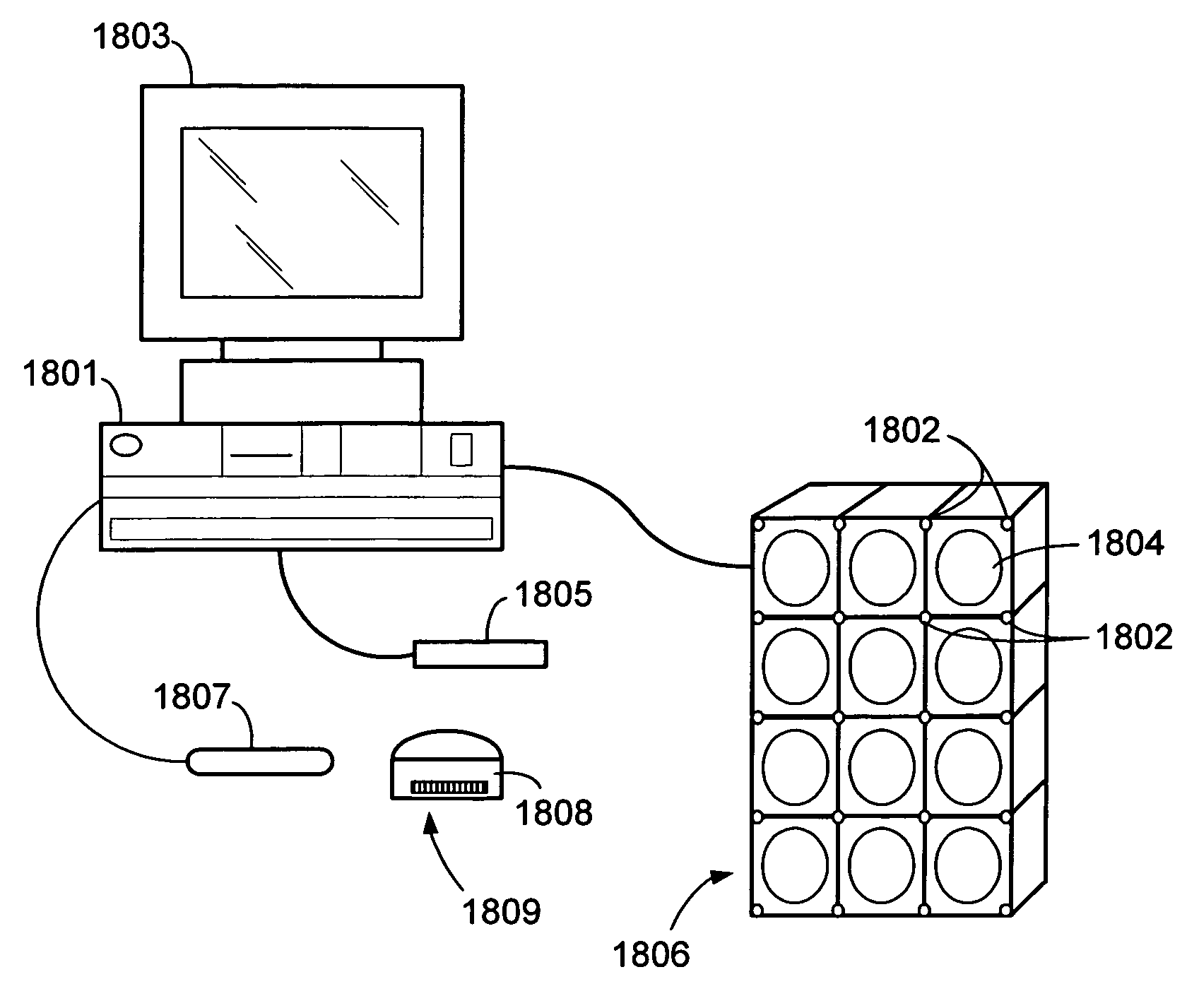
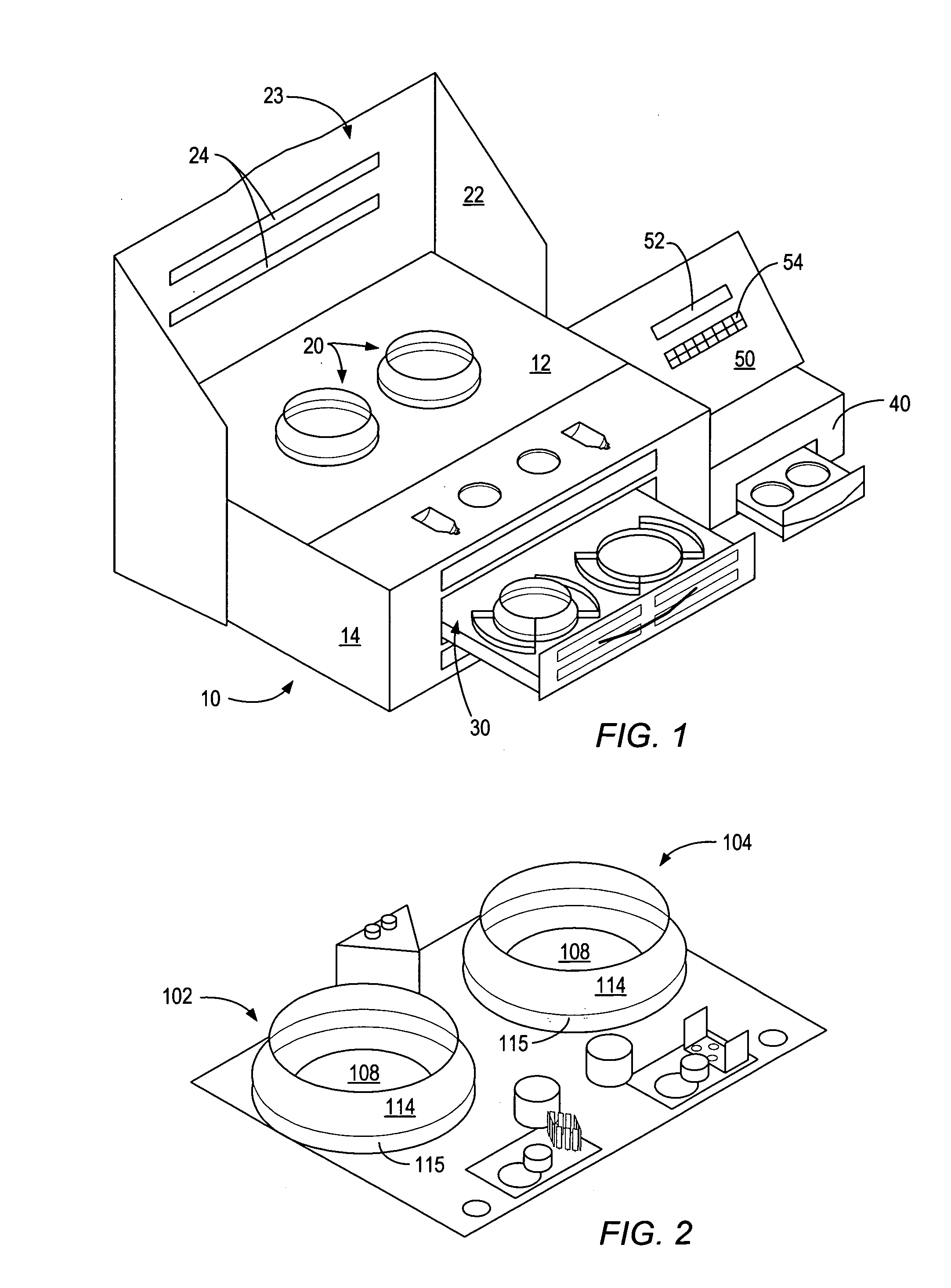
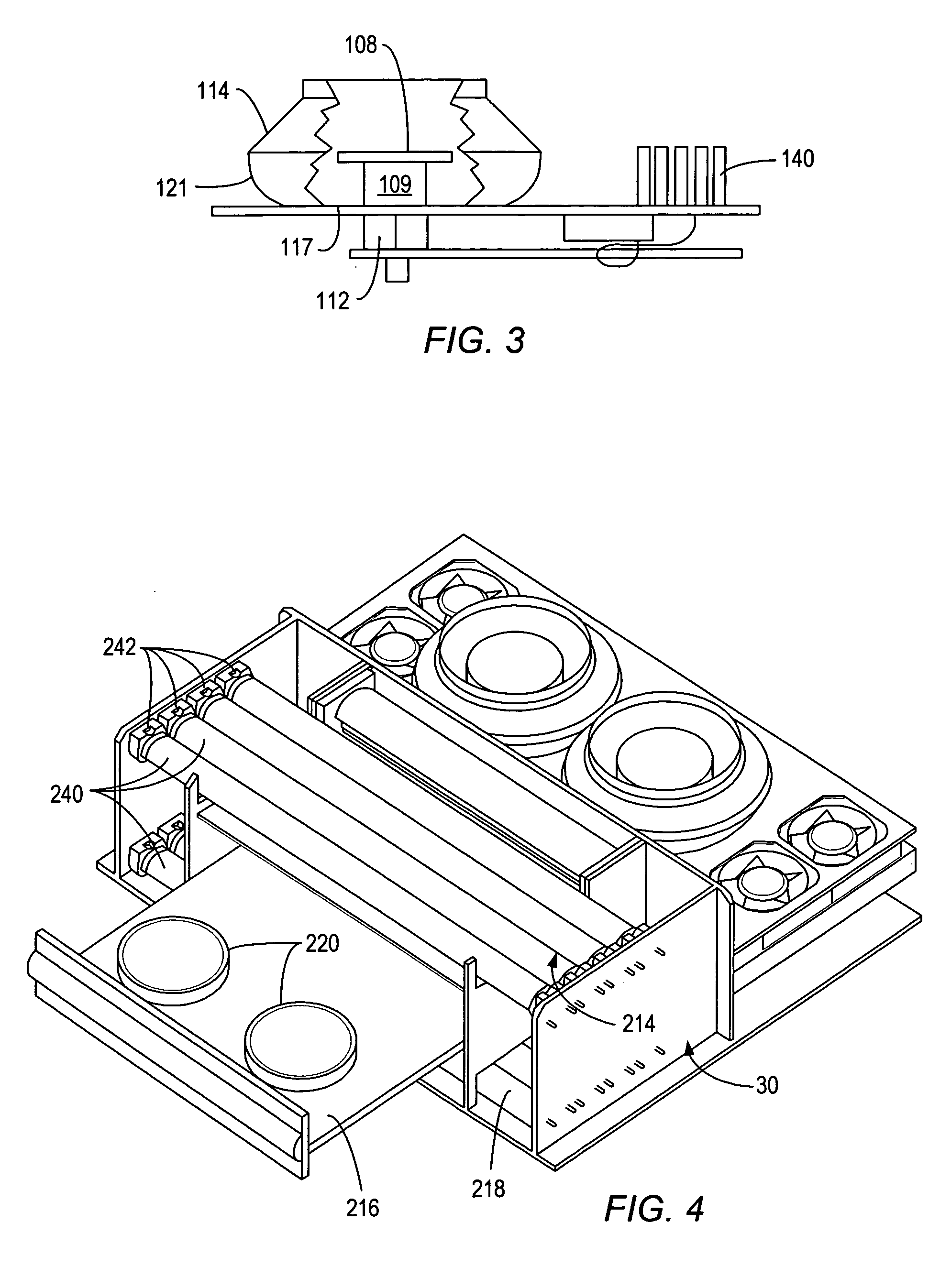
[0008]Embodiments disclosed herein, may allow mold members to be stored in an organized fashion. A controller may be utilized for processing and filing information about mold members, and their storage locations.
[0013]After use, a mold member may be placed back into an eyeglass mold member storage system. In an embodiment, a controller of an eyeglass mold member storage system may assist an operator in identifying a storage location associated with a mold member to be stored. For example, the operator may provide input to the controller identifying a mold member to be stored. The controller may determine a mold member storage location appropriate for storing the mold member. An indicator associated with a determined mold member storage location may be activated.

Problems solved by technology

As a result, locating specific eyeglass mold members to produce a particular eyeglass lens may be time consuming.
It may be difficult to visually distinguish one mold member from another.
Productivity may be lost if a mold is misplaced or cannot be located in a timely manner.
Accuracy may be lost if a mold member is misidentified.
After forming an eyeglass lens using a lens casting technique, separating the cast lens from one or more of the lens molds may be problematic.
Demolding may result in damage to the lens and / or one or more lens molds.

Method used


Image

  • Methods and systems for coating eyeglass lens molds
  • Methods and systems for coating eyeglass lens molds
  • Methods and systems for coating eyeglass lens molds

Examples


examples

[0577]A plastic eyeglass lens was made according to the process described above from the OMB-99 monomer solution. The lens was then coated with two antireflective coating compositions. In all of the examples, the following abbreviations are used:[0578]“AC” is acetone, commercially available from Aldrich;[0579]“AA” is an acrylic amine commercially available as CN384 from Sartomer;[0580]“Al” is aluminum tri-sec-butoxide (98%) commercially available from Avocado;[0581]“AS” is 3-aminopropyltrimethoxysilane (97%) commercially available from Aldrich;[0582]“BDK”, “BDM”, and “BDMK” are Photomer 51 and 2,2-dimethoxy-2-phenylacetophenone commercially available from Henkel;[0583]“BYK300” is a solution of polyether modified dimethylpolysiloxane copolymer commercially available from BYK Chemie;[0584]“CD1012” is diaryl iodonium hexafluoroantimonate commercially available from Sartomer;[0585]“CD540” is ethoxylated bisphenol A dimethacrylate commercially available from Sartomer;[0586]“CN124” is epo...


PUM

PropertyMeasurementUnit
Angleaaaaaaaaaa
Angleaaaaaaaaaa
Massaaaaaaaaaa

Abstract

Systems and methods for storing, locating, identifying and coating eyeglass lens mold members for use in the production of eyeglass lenses are disclosed. An embodiment includes storing eyeglass lens mold members in a storage array. A plurality of indicators may be coupled to the storage array and associated with storage locations. A controller may be configured to select mold members, and to identify the locations of the mold members. A user may input mold member identifying information. The controller may activate indicators associated with determined storage location. A mold reader may be used to input the mold member identifying information. The mold reader may detect a light pattern formed by illumination of the identifying information and determine the identity of the mold member based on the light pattern. Additional embodiments relate to separating a cast lens from a lens mold. Such embodiments may include a clamping mechanism for elastically deforming the lens mold. The lens mold and lens may then be separated by applying a separating force.

Description

BACKGROUND[0001]1. Field of the Invention[0002]Embodiments presented herein generally relate to eyeglass lenses. More particularly, embodiments relate to systems and methods for the location, storage, identification, and coating of eyeglass mold members used in the production of eyeglass lenses. Further embodiments relate to methods and systems for separating a cast lens from a lens mold.[0003]2. Description of the Relevant Art[0004]It is conventional in the art to produce eyeglass lenses by thermal curing techniques from the monomer of diethylene glycol bis(allyl)-carbonate (DEG-BAC). Eyeglass lenses may also be made using radiation curing techniques. In general, radiation techniques to form eyeglass lens may use one or more lens molds. Additionally, a mold gasket may be used. Lens molds may include spherical surfaces, toric surfaces or aspherical surfaces, and may contain other features as well in order to impart desired optical properties to a formed lens. Due to the lens thickne...

Claims


Application Information

Patent Timeline
IPC IPC(8): B29D11/00
CPCB29D11/00173Y10S425/808
Inventor FOREMAN, JOHN T.POWERS, GALEN R.LATTIS, MATTHEW C.
Owner Q2100
Learn More