
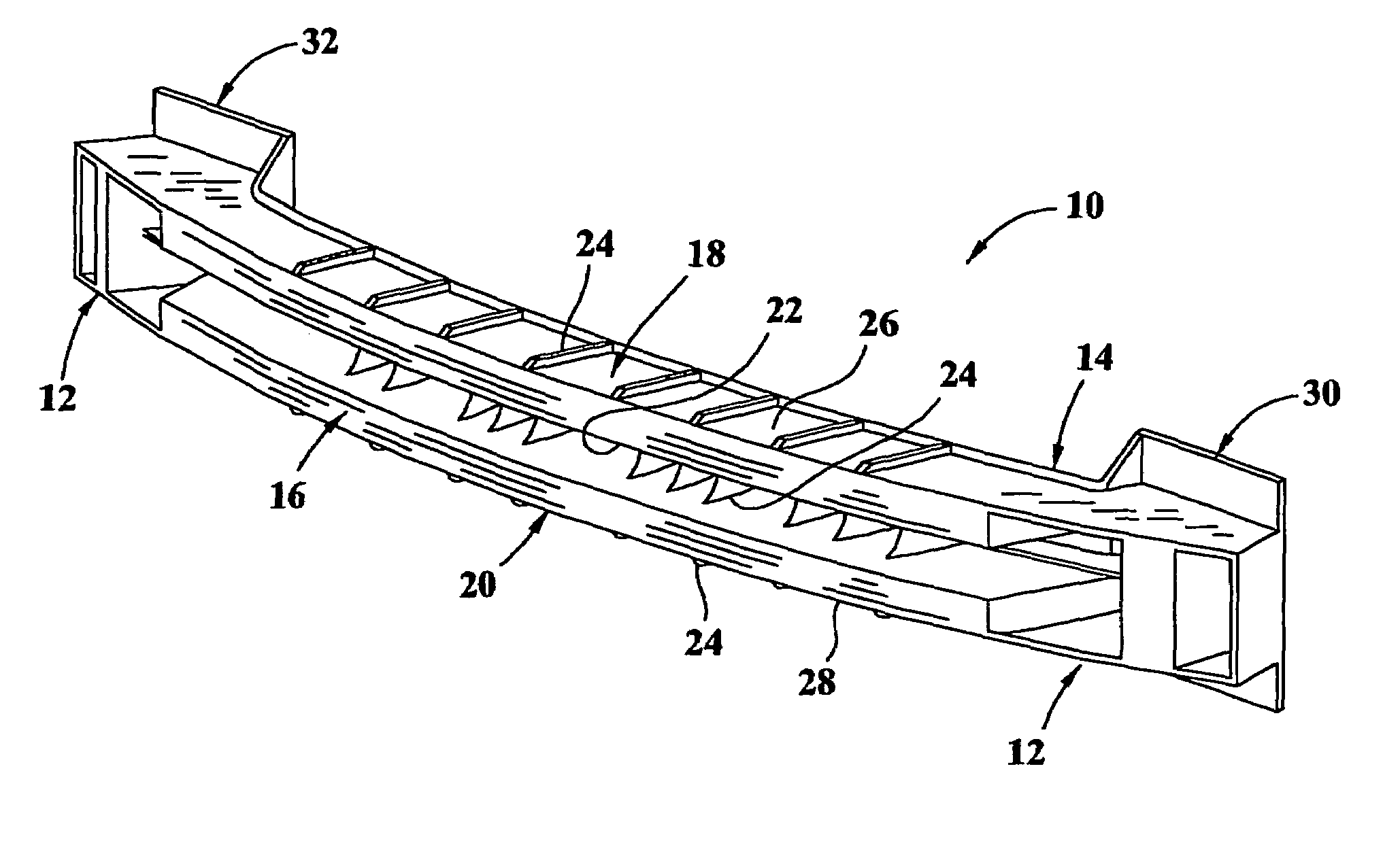
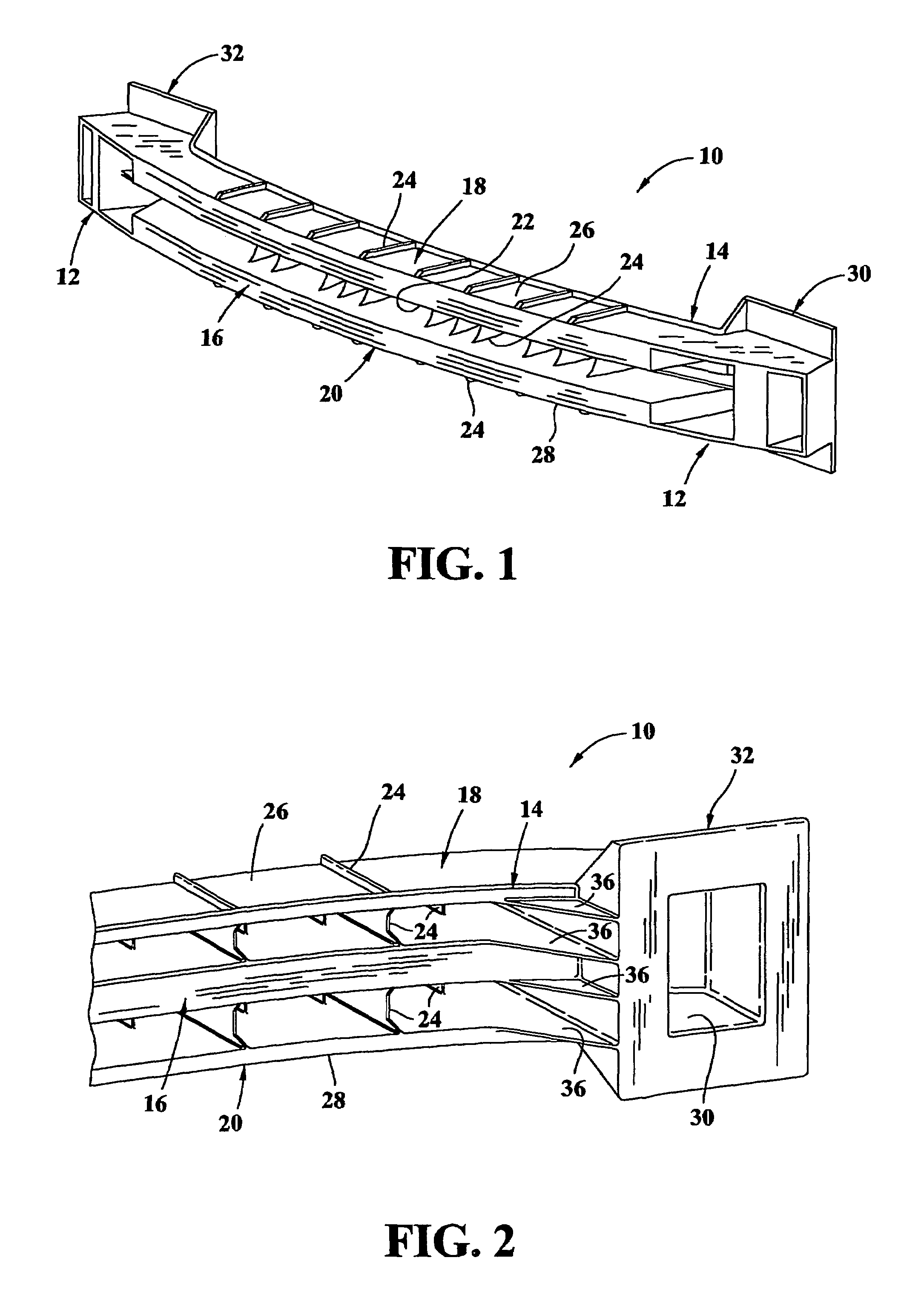
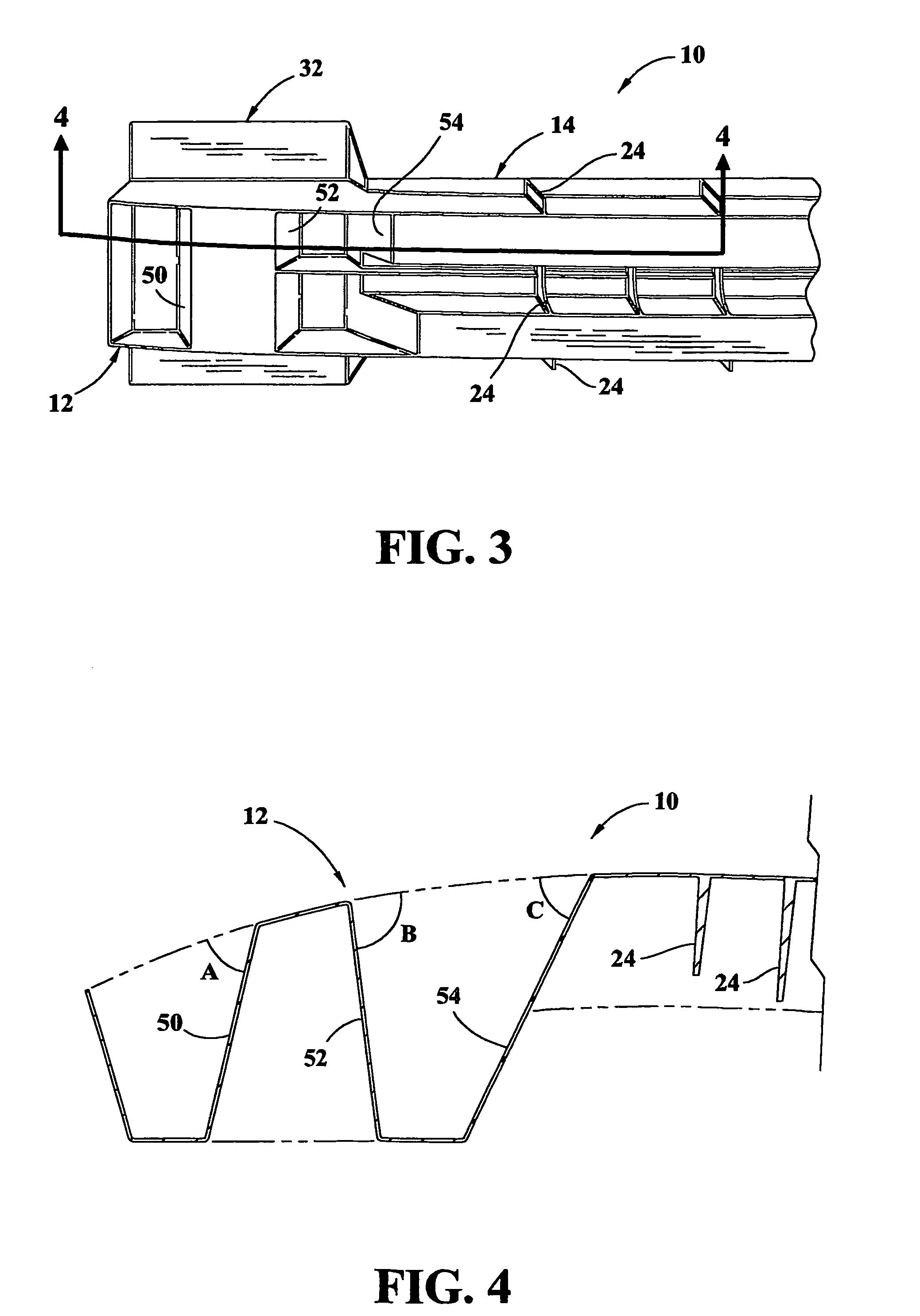
Bumper beam with crush cans

a technology of bumpers and cans, applied in the field of bumpers, can solve the problems of increased manufacturing deformation or buckle of steel beams, and additional damage to vehicles, and achieve the effects of increasing the fabrication and assembly costs of bumper assemblies

Inactive Publication Date: 2006-05-16
SABIC GLOBAL TECH BV
View PDF7 Cites 91 Cited by
  • Summary
  • Abstract
  • Description
  • Claims
  • Application Information

AI Technical Summary

Benefits of technology

The patent text describes a bumper assembly for an automotive vehicle that includes a beam and a fascia covering the beam. The beam has a crush can. Another aspect of the patent describes an energy absorbing beam that includes a frame and a body extending from the frame. The body has a first transverse wall, a second transverse wall, and at least one crush can between the first and second walls. The technical effect of this patent is to provide a bumper assembly that can absorb energy during a collision, reducing damage to the vehicle and ensuring safety for the occupants.

Problems solved by technology

Such steel beams are heavy and typically deform, or buckle, on impact.
Energy from an impact therefore may be transferred to the vehicle rails and result in additional damage to the vehicle.
Separately fabricating an energy absorber and assembling the energy absorber to the beam increases both the fabrication and assembly costs of a bumper assembly as compared to a simple steel beam bumper.
Foam based systems typically have slow loading upon impact, which results in a high displacement.
Further, foams are effective to a sixty or seventy percent compression, and beyond that point, foams become incompressible so that the impact energy is not fully absorbed.
Typically, as temperature is lowered, foam becomes more rigid, resulting in higher loads.
Conversely, as temperature rises, foams become more compliant resulting in higher displacements and possible vehicle damage.
Separately fabricating and attaching the crash cans to the beam, however, increases bumper assembly costs and complexity.

Method used


Image

  • Bumper beam with crush cans
  • Bumper beam with crush cans
  • Bumper beam with crush cans

Examples


Embodiment Construction

[0014]A thermoplastic bumper beam that includes tunable crush cans is described below in detail. The term tunable, as used herein, means that characteristics, e.g., wall angles, of the crush cans can be selected to provide a desired operating result, as described below in more detail. The crush cans are sometimes described herein as being integral with the beam, which means that the crush cans are formed as a component of, and not separately from, the beam, which results in a one-piece unitary structure for the beam. The term integral also includes constructions in which the beam is molded in segments, and then the segments are secured together, e.g., welded.

[0015]Combining the crush cans with the beam results in a bumper system that absorbs energy without necessitating a separate energy absorber attached to the beam. For example, impact forces during low speed impacts are maintained just below a predetermined level by deforming the beam until the kinetic energy of the impact event ...


PUM


Abstract

A bumper assembly (10) for an automotive vehicle is described. In an example embodiment, the assembly comprises a beam and a fascia at least partially covering the beam. The beam comprises at least one crush can (12).

Description

CROSS REFERENCE TO RELATED APPLICATIONS[0001]This application claims the benefit of International Application No. PCT / US01 / 28583 filed Sep. 12, 2001.BACKGROUND OF THE INVENTION[0002]This invention relates generally to bumpers and, more particularly, to bumper beams.[0003]Bumpers typically extend widthwise across the front and rear of a vehicle and are mounted to rails that extend in a lengthwise direction. A typical bumper includes a steel beam or reinforcing member attached to vehicle rails and covered by a fascia. Such steel beams are heavy and typically deform, or buckle, on impact. Energy from an impact therefore may be transferred to the vehicle rails and result in additional damage to the vehicle.[0004]Energy absorbing bumper systems attempt to reduce vehicle damage as a result of a collision by managing impact energy and intrusion while not exceeding a rail load limit of the vehicle. The efficiency of a bumper system is defined as the amount of energy absorbed over distance. ...

Claims


Application Information

Patent Timeline
Patent Type & Authority Patents(United States)
IPC IPC(8): B60R19/03B60R19/18
CPCB60R19/18B60R2019/1846B60R2019/1813B60R2019/1853B60R2019/1866A61M5/14212A61M5/16804A61M2205/18B60R19/34A61M5/142A61M31/00
Inventor MOOIJMAN, FRANKMCMAHON, DOMINICSANTHANAM, SRIKANTH M.
Owner SABIC GLOBAL TECH BV
Learn More