
Optical illusion speed bump and method of using the same

a technology of optical illusion and speed bump, which is applied in the direction of signalling system, roads, constructions, etc., can solve the problems of control devices, damage to the suspension of the vehicle, and negatively affecting even those drivers

Inactive Publication Date: 2006-05-16
GROFF BRADLEY K
View PDF10 Cites 10 Cited by
  • Summary
  • Abstract
  • Description
  • Claims
  • Application Information

AI Technical Summary

Benefits of technology

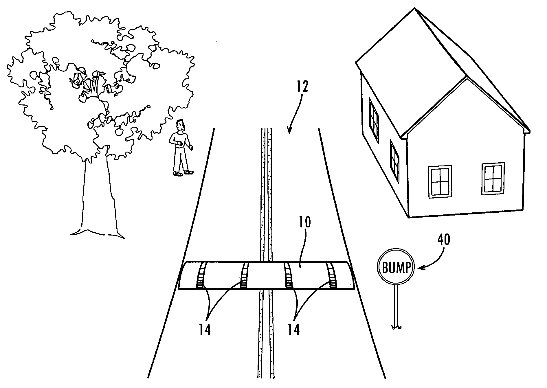
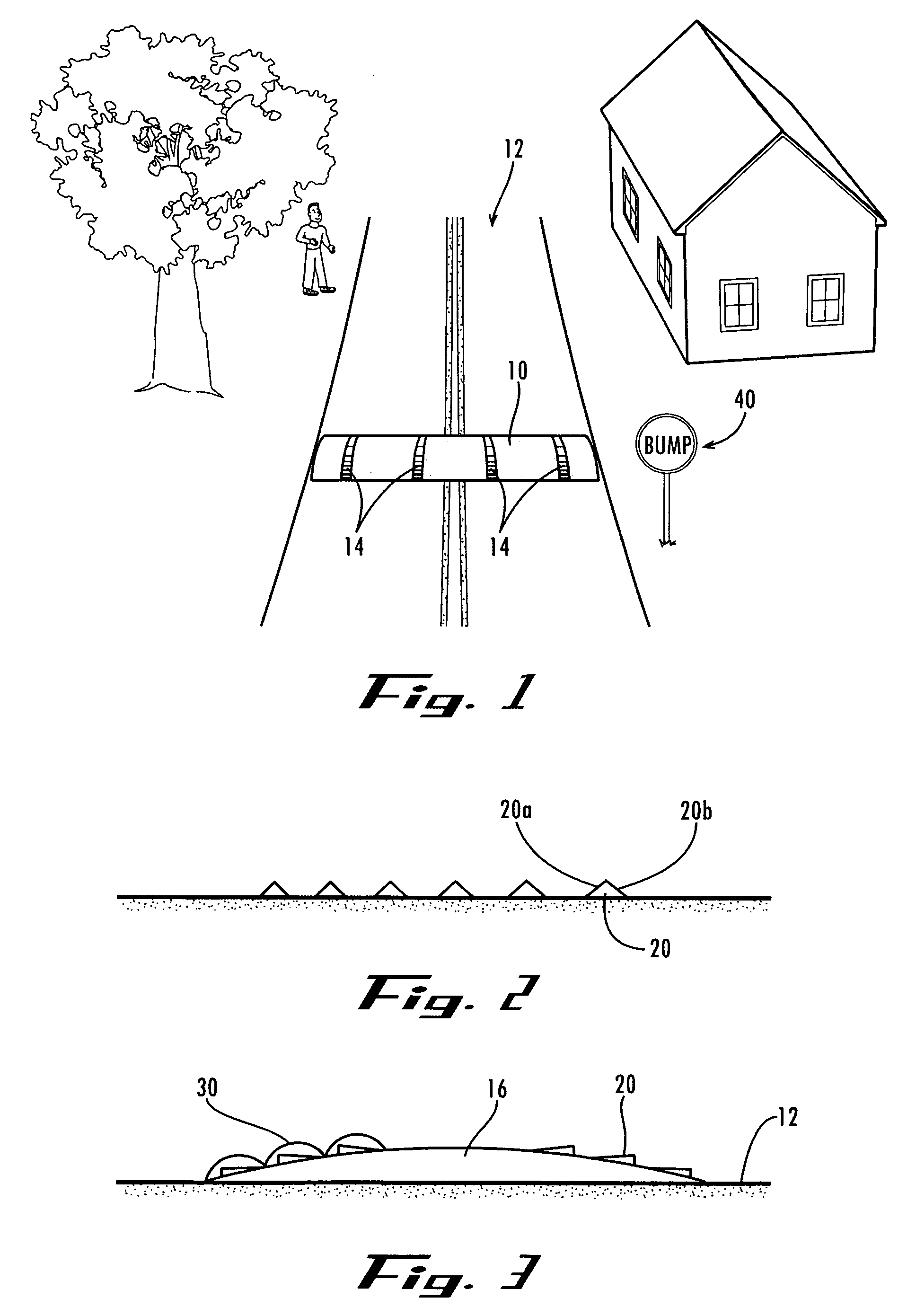
[0005]The present invention provides an improved method and device for vehicle speed control. The present invention takes advantage of non-resident drivers' unfamiliarity with neighborhood roadways, without subjecting residents and those familiar with the roadways to undue inconvenience and annoyance. The method and device of the present invention utilize a visually enhanced speed bump or a visually created simulated speed bump (i.e., an optical illusion) to control vehicle speed. Those unfamiliar with the roadway will not know that an upcoming speed bump is visually enhanced or optically simulated, and will slow down as if they were approaching a normal speed bump. Those familiar with a neighborhood will come to know which speed bumps are real and which are optically simulated or enhanced, and will be less inconvenienced thereby.

Problems solved by technology

These speed control devices, however, negatively affect even those drivers who are obeying the speed limit yet still must tolerate the discomfort or annoyance caused by bouncing over the speed bump.
Repeated travel over speed bumps may also damage a vehicle's suspension or cause accelerated wear of vehicle components.
Also, increased traffic noise is often generated as vehicles impact a speed bump, and as vehicles decelerate before a speed bump and accelerate after a speed bump.
Rather, the worst offenders of the speed limit laws are often non-residents cutting through a neighborhood, or visitors to the neighborhood.
These speeding non-residents are all the more dangerous, as they typically do not know the roadways, traffic patterns or surroundings of a neighborhood as well as do the neighborhood's residents.

Method used


Image

  • Optical illusion speed bump and method of using the same
  • Optical illusion speed bump and method of using the same

Examples


Embodiment Construction

[0013]Referring now to the drawing figures, wherein like reference numerals represent like parts throughout, preferred forms of the present invention will now be described. As seen best with reference to FIGS. 1–3, one form of the invention is a simulated or optically enhanced speed bump 10 provided on a roadway 12.

[0014]The simulated or optically enhanced speed bump 10 preferably comprises at least one visually perceptible feature 14 applied on a portion of the roadway, whereby the at least one visually perceptible feature simulates the appearance of a speed bump to oncoming traffic, or enhances the appearance of an actual speed bump of the roadway. The visually perceptible feature 14 can take a number of forms, such as for example: a portion of the roadway painted to create the optical illusion of a speed bump in the roadway where none actually exists; a painted or printed image applied to an actual speed bump to create the illusion of a speed bump of greater size or steeper impac...


PUM


Abstract

A speed control method and device. A speed bump is optically simulated on a roadway as by painting the roadway to create the appearance of a real speed bump, or an actual speed bump is visually enhanced to appear larger than it actually is. Actual speed bumps can be randomly interspersed among simulated speed bumps along a roadway.

Description

FIELD OF THE INVENTION[0001]The present invention relates generally to traffic control methods and devices; and more particularly to a speed bump that is optically enhanced or simulated.BACKGROUND OF THE INVENTIONDescription of Related Art[0002]Speed control devices such as speed bumps or road humps are utilized to discourage speeding in residential neighborhoods. These speed control devices, however, negatively affect even those drivers who are obeying the speed limit yet still must tolerate the discomfort or annoyance caused by bouncing over the speed bump. Repeated travel over speed bumps may also damage a vehicle's suspension or cause accelerated wear of vehicle components. Also, increased traffic noise is often generated as vehicles impact a speed bump, and as vehicles decelerate before a speed bump and accelerate after a speed bump.[0003]Residents generally do not speed dangerously through their own neighborhood. Rather, the worst offenders of the speed limit laws are often no...

Claims


Application Information

Patent Timeline
IPC IPC(8): G08B5/00E01F9/529
CPCE01F9/047E01F9/529
Inventor GROFF, BRADLEY K.
Owner GROFF BRADLEY K
Learn More