Load cup for chemical mechanical polishing

a technology of mechanical polishing and loading cup, which is applied in the direction of lapping machines, grinding machine components, manufacturing tools, etc., can solve the problems of substrate damage and substantially disrupting process throughpu

Active Publication Date: 2006-05-16
APPLIED MATERIALS INC
View PDF21 Cites 83 Cited by
  • Summary
  • Abstract
  • Description
  • Claims
  • Application Information

AI Technical Summary

Problems solved by technology

Any misalignment between the substrate and the load cup may result in substrate damage.
Moreover, if the substrate is not successfully de-chucked, but is retained in the polishing head, the de-chucking process must be repeated before additional substrates can be processed, which substantially disrupts process throughput.

Method used


Image

  • Load cup for chemical mechanical polishing
  • Load cup for chemical mechanical polishing
  • Load cup for chemical mechanical polishing

Examples


Embodiment Construction

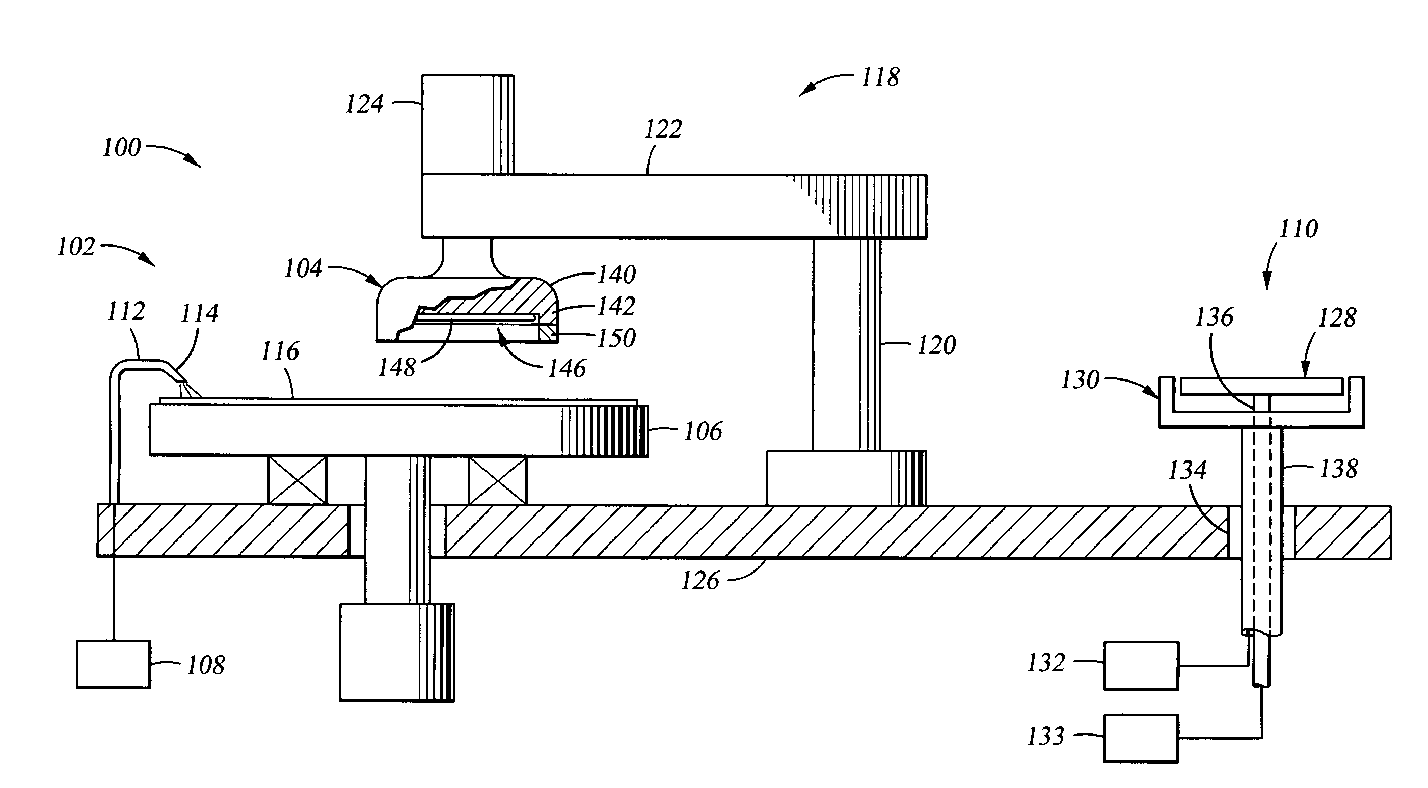
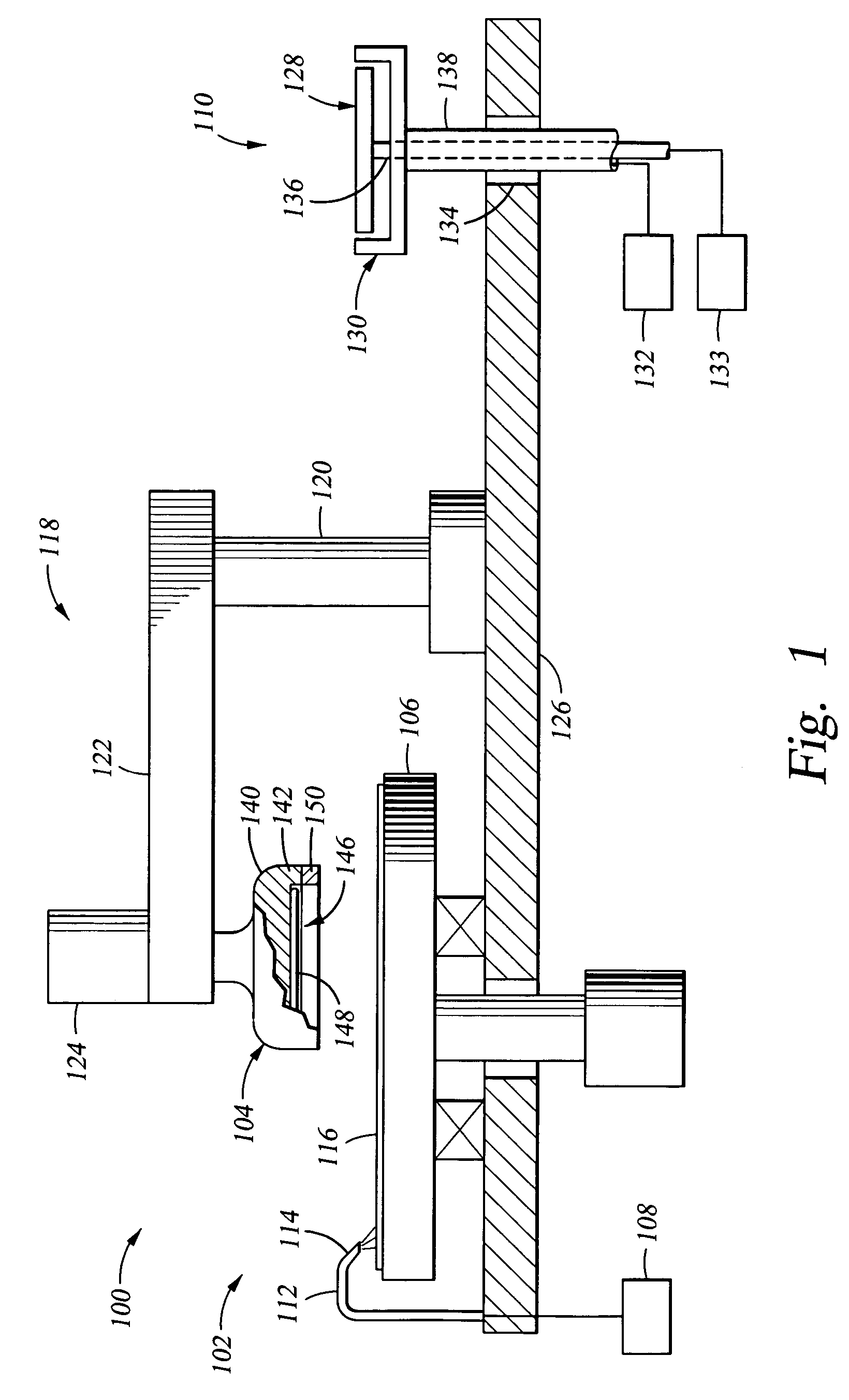
[0023]FIG. 1 depicts a partially sectional view of a simplified chemical mechanical polishing system 100 that includes a polishing station 102, a polishing head 104 and one embodiment of a load cup 110 of the present invention. Although the load cup 110 is shown in one embodiment of a polishing system 100, the load cup 110 may be utilized in any polishing system including electrically assisted polishing systems currently being developed for conductive layer polishing, and any other processing system that utilizes a substrate-retaining head to retain a substrate in a face down orientation during processing. Examples of suitable polishing systems which may be adapted to benefit from the invention include MIRRA® and REFLEXION® chemical mechanical polishing systems available from Applied Materials Inc., located in Santa Clara, Calif. Other polishing systems that may be adapted to benefit from the invention include systems described in U.S. Pat. No. 5,738,574, issued Apr. 14, 1998 to Tol...


PUM


Abstract

Embodiments of a load cup for transferring a substrate are provided. The load cup includes a pedestal assembly having a substrate support and a de-chucking nozzle. The de-chucking nozzle is positioned to flow a fluid between the polishing head and the back side of a substrate during transfer of the substrate from the polishing head to the substrate support.

Description

CROSS-REFERENCE TO RELATED APPLICATIONS[0001]This application claims the benefit of now abandoned U.S. Provisional Patent Application Ser. No. 60 / 520,611, filed on Nov. 17, 2003, which is incorporated by reference herein.BACKGROUND OF THE INVENTION[0002]1. Field of the Invention[0003]Embodiments in the invention generally relate to a substrate transfer mechanism (e.g., a load cup) for transferring a substrate to and from a polishing head in a chemical mechanical polishing system.[0004]2. Background of the Related Art[0005]Chemical mechanical polishing (CMP) is one of many processes used in the fabrication of high density integrated circuits. Chemical mechanical polishing is generally performed by moving a substrate against a polishing material in the presence of a polishing fluid. In many polishing applications, the polishing fluid contains an abrasive slurry to assist in the planarization of the feature side of the substrate that is pressed against the polishing material during pro...

Claims


Application Information

Patent Timeline
Patent Type & Authority Patents(United States)
IPC IPC(8): B24B49/00B24B37/04
CPCB24B37/345
Inventor YILMAZ, ALPAYYAVELBERG, SIMONTOMITA, TOSHIKAZUCHEN, HUIMANTO, NOELLISCHKA, DAVID J.CHEN, HUNG CHIH
Owner APPLIED MATERIALS INC
Why Eureka
Try Eureka