Apparatus and method for ultrasonic diagnostic imaging

a diagnostic apparatus and ultrasonic technology, applied in the field of ultrasonic diagnostic apparatus, can solve the problems of low intensity of nonlinear propagation components generated from tissue, collapse of microbubbles in contrast medium used for ultrasonic diagnosis, and collapse of microbubbles, etc., and achieve the effect of high frame ra

Inactive Publication Date: 2006-05-16
TOSHIBA MEDICAL SYST CORP
View PDF15 Cites 10 Cited by
  • Summary
  • Abstract
  • Description
  • Claims
  • Application Information

AI Technical Summary

Problems solved by technology

Microbubbles contained in a contrast medium used for ultrasonic diagnosis are collapsed by ultrasonic transmission and tend be collapsed when the transmitted sound pressure is higher.
When the sound pressure is low as in RPI, the nonlinear propagation component generated from the tissue has very low intensity, which is insufficient for imaging.
Particularly, this problem is noticeable at the time of ultra-low sound pressure driving where an MI (mechanical index) value, which is an index showing an output reference obtained by normalizing a maximum peak negative sound pressure in a transmitted beam by the square root of the fundamental frequency, is approximately 0.1.
However, since separate transmissions and receptions are necessary for the tissue and for the contrast, respectively, the frame rate, which is particularly important for imaging a cardiovascular system, is lowered and the real-time property cannot be utilized.
Moreover, the transmission for the tissue may cause unwanted collapse of and adverse effects on the contrast medium.
When an image is generated using only a harmonic component with a low MI value, even if contrast-enhancement is performed, the brightness of the image is low and it may be difficult to confirm the enhanced region.
If the gain is increased only to increase the brightness, noise appears in the image.
Even if the dynamic range is narrowed to brighten a maximum brightness part, only a part having relatively high brightness is emphasized and the contrast-enhancement cannot be correctly evaluated.

Method used


Image

  • Apparatus and method for ultrasonic diagnostic imaging
  • Apparatus and method for ultrasonic diagnostic imaging
  • Apparatus and method for ultrasonic diagnostic imaging

Examples


Embodiment Construction

[0040]Referring now to the drawings, wherein like reference numerals designate the same or corresponding parts throughout the several views, various embodiments of this invention will now be described.

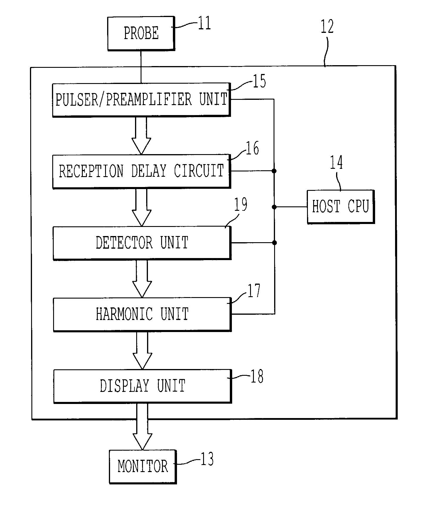
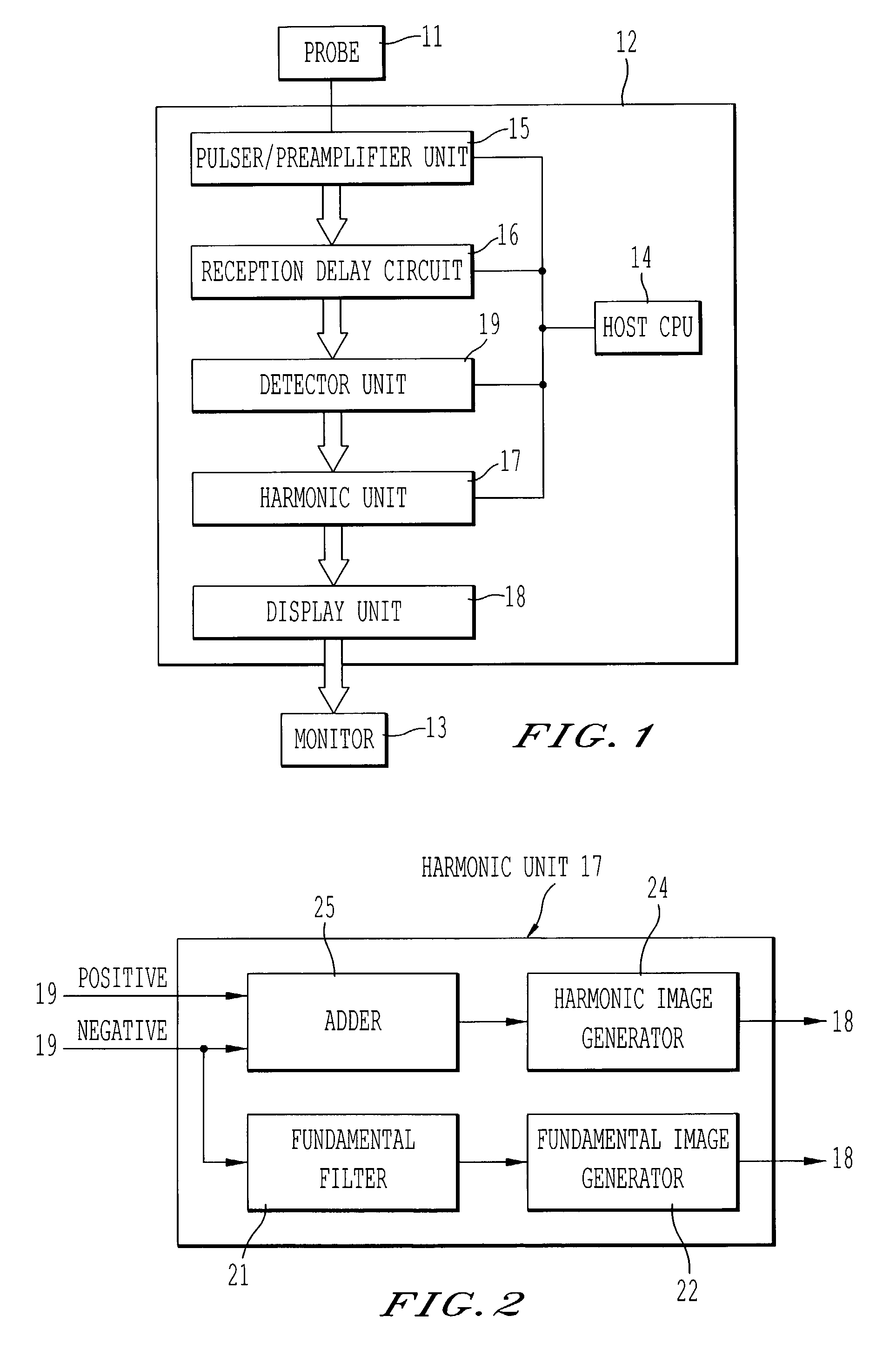
[0041]FIG. 1 shows a structure of an ultrasonic diagnostic apparatus according to one embodiment. Reference numeral 11 denotes an ultrasonic probe including plural transducer elements (electroacoustic transducer elements) arranged one-dimensionally or two-dimensionally and typically utilizing a piezoelectric effect. The ultrasonic probe 11 is connected to an apparatus body 12 having a host CPU 14 as its main part, via a connector, not shown. One or neighboring several transducer elements constitute one channel. It is now assumed that one transducer element constitute one channel. To the transducer elements of this ultrasonic probe 11, transmission pulse voltage is applied from a pulser / preamplifier unit 15 under a transmission condition that MI is 0.6 or less. The transducer elements c...


PUM


Abstract

An ultrasonic diagnosis apparatus and method wherein both imaging of a contrast effect and imaging of a tissue appearance before and after inflow of a contrast medium can be realized on condition that low-power transmission and a high frame rate are maintained. The ultrasonic diagnostic apparatus includes a transmission / reception unit for transmitting subject ultrasonic waves with a band substantially centered at a fundamental frequency and generating a received signal based on an ultrasonic echo from the subject, a harmonic unit for extracting a signal of a harmonic component of the fundamental frequency included in the received signal and extracting a signal of the fundamental component with the band substantially centered the fundamental frequency included in the received signal, and a display unit for generating a display image based on the extracted harmonic and fundamental components.

Description

CROSS-REFERENCE TO RELATED APPLICATIONS[0001]This application is based upon and claims the benefit of priority from the prior Japanese Patent Application No. 2002-32770, filed Feb. 8, 2002, the entire contents of which are incorporated herein by reference.BACKGROUND OF THE INVENTION[0002]1. Field of the Invention[0003]This invention relates to an ultrasonic diagnostic apparatus, and particularly to a contrast medium imaging technique.[0004]2. Description of the Related Art[0005]Microbubbles contained in a contrast medium used for ultrasonic diagnosis are collapsed by ultrasonic transmission and tend be collapsed when the transmitted sound pressure is higher. To maintain a contrast effect, a certain measure needs to be taken such as imaging a contrast medium while suppressing its collapse by using a low sound pressure (real-time perfusion image or RPI).[0006]The case of extracting a second harmonic component of a transmitted fundamental wave from a received echo in RPI will now be co...

Claims


Application Information

Patent Timeline
Patent Type & Authority Patents(United States)
IPC IPC(8): A61B8/00A61B8/14G01S7/52G01S15/10
CPCG01S15/8963G01S7/52038G01S7/52026G01S15/102
Inventor KAWAGISHI, TETSUYAMINE, YOSHITAKAKURITA, KOICHIROOYANAGI, MASAMICHI
Owner TOSHIBA MEDICAL SYST CORP
Why Eureka
Try Eureka