Video signal converting apparatus and method

a technology of video signal and converting apparatus, which is applied in the direction of signal generator with optical-mechanical scanning, picture reproducing device, television system, etc., can solve the problems of flickering, poor picture quality, and inability to obtain better image quality

Inactive Publication Date: 2005-01-06
PIONEER CORP
View PDF12 Cites 51 Cited by
  • Summary
  • Abstract
  • Description
  • Claims
  • Application Information

AI Technical Summary

Benefits of technology

[0011] According to an aspect of the invention, there is provided a video signal converting apparatus for converting an input video signal to a progressive video signal having a high frame rate, the apparatus including an interlace discriminating component for discriminating whether the input video signal is an interlaced video signal or not, a film source discriminating component for discriminating whether the input video signal is a video signal from a film source based on a film, an interlace/progressive converting component for converting, for outputting, the input video signal to the progressive video signal by a converting method in accordance with a discrimination result by the film source discriminating component if the interlace discriminating component discriminates that the input video signal is an interlaced video signal and for outputting the input video signal as it is if the interlace discriminating component discriminates that the input video signal is not an interlaced video signal, and a frame rate converting component for converting an output video signal from the interlace/progressive converting component to a video signal having a high frame rate in accordance with the discrimination result by the film source discriminating comp

Problems solved by technology

Incidentally, when a picture with interlaced-scanned video signals resulting from telecine conversion is displayed on a display apparatus such as a PDP, the quality of the picture become poorer than that of the original movie film.
On the other hand, even if the video

Method used


Image

  • Video signal converting apparatus and method
  • Video signal converting apparatus and method
  • Video signal converting apparatus and method

Examples


Embodiment Construction

[0018] An embodiment of the invention will be described below in detail with reference to drawings.

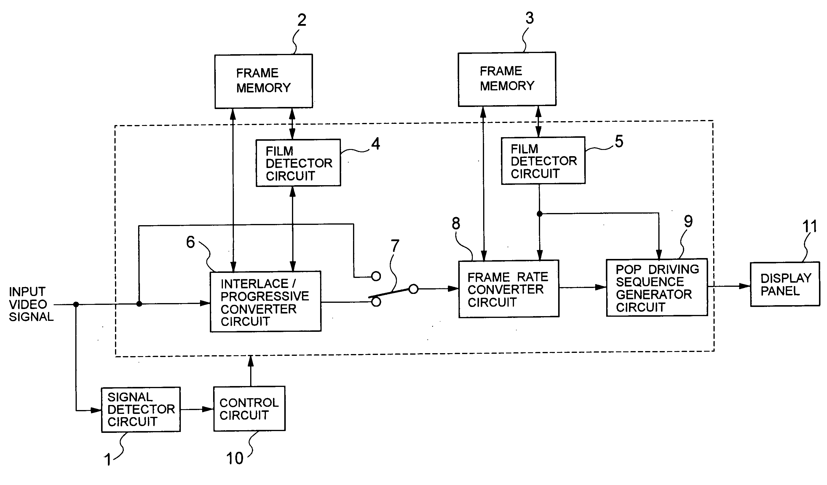
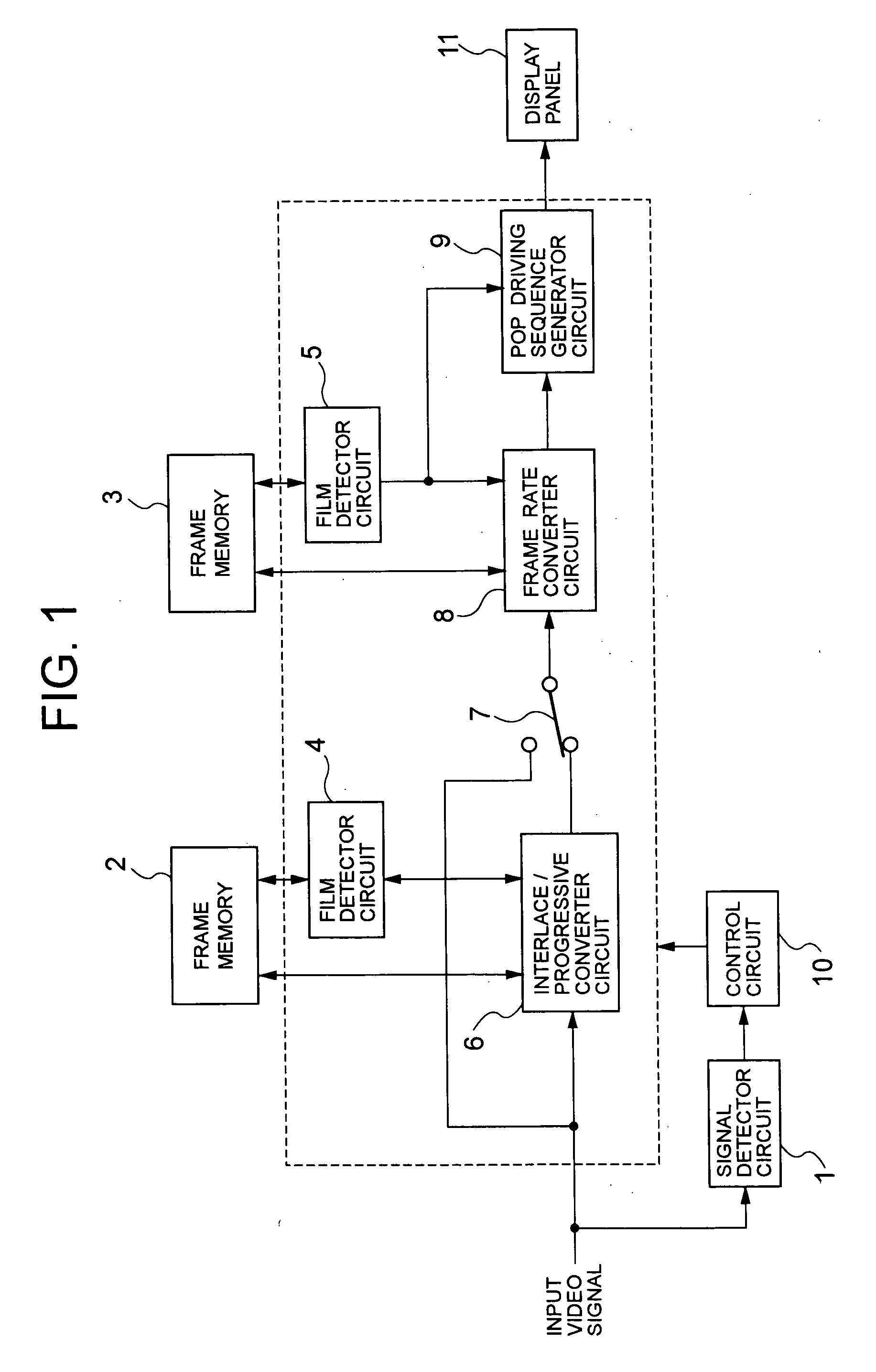
[0019]FIG. 1 shows a video signal converting apparatus of the invention. The video signal converting apparatus includes a signal detector circuit 1, frame memories 2 and 3, film detector circuits 4 and 5, an interlace / progressive converter circuit 6, a select switch 7, a frame rate converter circuit 8, a PDP-driving sequence generator circuit 9 and a control circuit 10.

[0020] The signal detector circuit 1 detects a synchronizing signal of the input video signal and discriminates a signal format of the video signal. The signals processable by the converting apparatus according to this embodiment include a video signal in the NTSC system, a video signal in the PAL system, a 525 scan line progressive video signal, a 625 scan line progressive video signal, a 750 scan line progressive video signal at the vertical synchronizing frequency fv of 50 / 60 Hz, a 1125 scan line interlaced video si...


PUM


Abstract

A video signal converting apparatus and method for improving display quality of video signals from both film source and video source. It is discriminated whether the input video signal is an interlaced video signal or not, and it is discriminated whether the input video signal is a video signal from a film source based on a film. If the input video signal is discriminated as interlaced video signals, the input video signal is converted, for outputting, to the progressive video signals by a converting method in accordance with a discrimination result regarding whether the input video signal is a video signal from the film source or not. The converted progressive video signal is converted, for outputting, to a video signal having a high frame rate in accordance with the discrimination result regarding whether the converted progressive video signal is a video signal from the film source or not. If the input video signal is not discriminated as an interlaced video signal, the input video signal is converted to a video signal having a high frame rate in accordance with a discrimination result regarding whether the input video signal is a video signal from the film source or not.

Description

BACKGROUND OF THE INVENTION [0001] 1. Field of the Invention [0002] The present invention relates to a video signal converting apparatus for converting an input video signal so as to be displayed on a display apparatus in high quality. [0003] 2. Description of the Related Art [0004] Among video signals in a standard television system such as the NTSC system, a video signal from a film source based on a movie film is used occasionally. A movie film includes 24 frames per second while a video signal in a standard television system include 30 frames per second and is a video signal of interlaced scanning having frames each including two fields. Since the numbers of frames per second differ, each frame of a movie film is telecine-converted with a 2-3 pull-down process so that a video signal in the standard television system can be generally obtained. [0005] With the 2-3 pull down process, first and second fields of a first frame of a video signal are created from a first frame of a movi...

Claims


Application Information

Patent Timeline
IPC IPC(8): H04N7/01
CPCH04N7/012H04N7/0112
Inventor OCHIAL, KAZUNORIANDO, HIROSHISHIGETA, TETSUYANAGAKUBO, TETSURO
Owner PIONEER CORP
Why Eureka
Try Eureka