
Method for optical flow field estimation using adaptive Filting

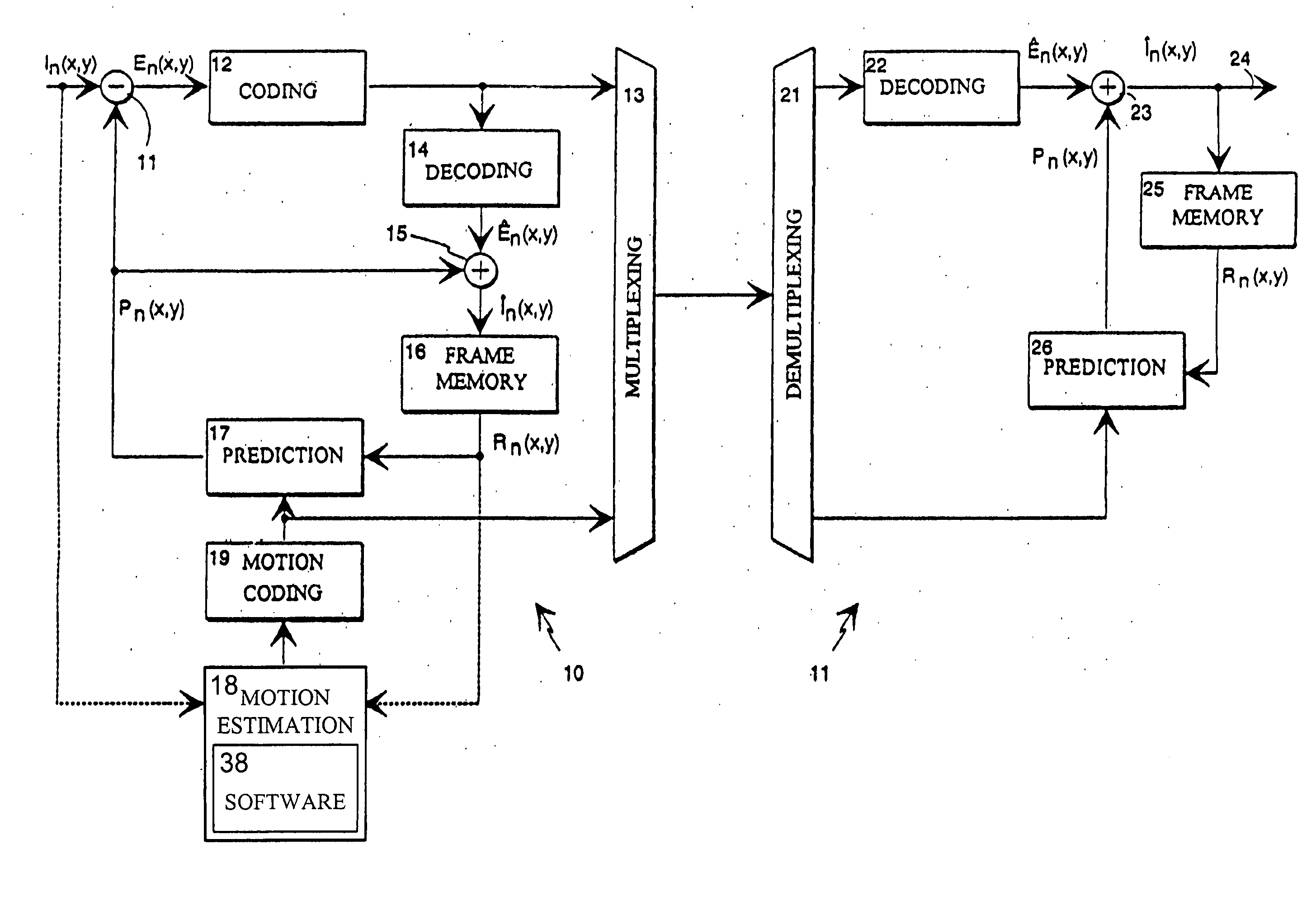
a flow field and adaptive filting technology, applied in the field of motion estimation, can solve the problems of inefficient direct application of block-based motion estimation in filtering applications such as video image deblurring and noise reduction, and the known methods for estimation of dense optical fields are typically computationally complex

Inactive Publication Date: 2007-07-26
NOKIA CORP
View PDF2 Cites 50 Cited by
  • Summary
  • Abstract
  • Description
  • Claims
  • Application Information

AI Technical Summary

Benefits of technology

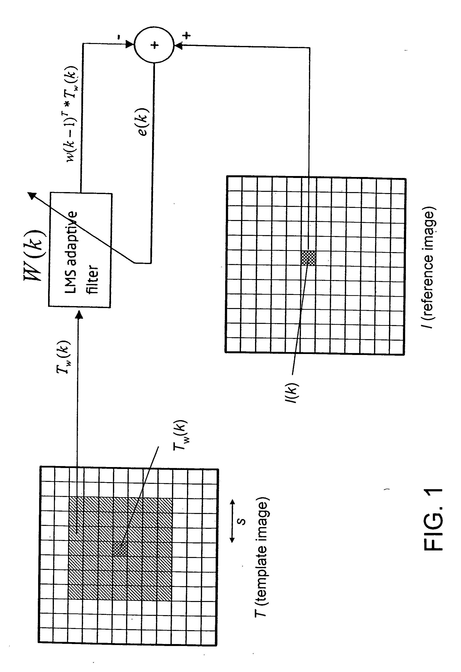
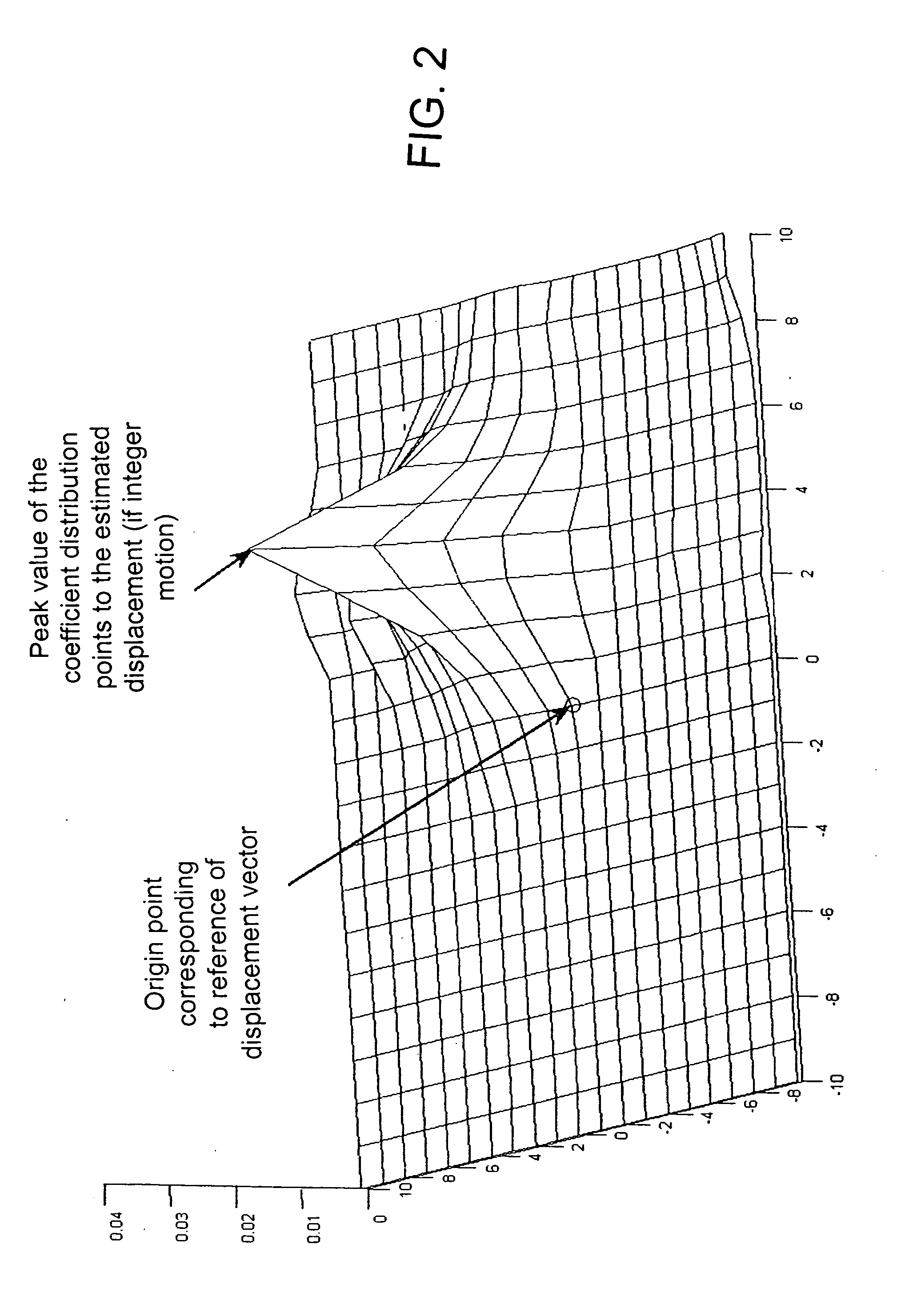
[0008] The present invention obtains motion vectors by recursively adapting a set of coefficients using a least mean square (LMS) filter, while consecutively scanning through individual pixels in any given scanning direction. The LMS filter, according to the present invention, is a pixel-wise algorithm that adapts itself recursively to match the pixels of an input image to those in a reference image. This matching is performed through the smooth modulation of the filter coefficient matrix as the scanning advances. The distribution of the adapted filter coefficients is used to determine the displacement of each pixel in the input image with resp

Problems solved by technology

However, the drawbacks are that block-matching fails to catch detailed motion of a deformable-body and the result of block-matching does not necessarily reflect real motion.
Because of its poor motion prediction along the moving boundaries, direct application of block-based motion estimation in filtering applications such as video image deblurring and noise reduction is relatively inefficient.
Known methods for estimation of dense optical field are typically computationally complex, and hence not suitable for real-time applications.

Method used


Image

  • Method for optical flow field estimation using adaptive Filting
  • Method for optical flow field estimation using adaptive Filting
  • Method for optical flow field estimation using adaptive Filting

Examples


Embodiment Construction

[0016] The present invention involves registering a template image T in a target frame with respect to a reference image I in a reference frame. These two images are usually two successive frames of a video sequence. Both images are defined over the discrete grid positions k=[x,y]T,where 0≦x<X, 0≦y<Y. The image intensities are denoted by I(k) for the reference image and T(k) for the template image. The dense flow field is estimated based on the displacement between the target frame and the reference frame that happened in the corresponding time interval, and is defined as:

D(k)=[u(k),v(k)]T.   (1)

[0017] Here D(k) is the displacement vector which need not be an integer valued, and u(k) and v(k) are the corresponding horizontal and vertical components over the two-dimensional grid. With a constrained motion, D(k) is limited by {-s≤u⁡(k)≤s-s≤v⁡(k)≤s 

where 2*s+1 is the size of a search area or window that is centered at pixel location T(k) in the template image. The pixels inside thi...


PUM


Abstract

A motion estimation process in video coding takes into account the estimates in the immediate spatio-temporal neighborhood, through an adaptive filtering mechanism, in order to produce a smooth and coherent optical flow field at each pixel position. The adaptive filtering mechanism includes a recursive LMS filter based on pixel-wise algorithm for obtaining motion vectors in a reference image of a video image frame, while consecutively scanning through individual pixels of the image frame. This motion estimation process is particularly well suited for the estimation of small displacements within consecutive video frames, and can be applied in several applications such as super-resolution, stabilization, denoising of video sequences. The method is also well suited for high frame rate video capture.

Description

FIELD OF THE INVENTION [0001] The present invention relates generally to motion estimation and, more particularly, to optical flow estimation in the raw video domain. BACKGROUND OF THE INVENTION [0002] Motion estimation and image registration tasks are fundamental to many image processing and computer vision applications. Model-based image motion estimation has been used in 3D image video capture to determine depth maps from 2D images. In computer vision, motion estimation has been used for image pixel registration. Motion estimation has also been used for object recognition and segmentation. Two major approaches have been developed for solving various problems in motion estimation: block matching or discrete motion estimation, and optical field estimation. [0003] Motion estimation establishes the correspondences between the pixel positions from a target frame with respect to a reference frame. With block-matching, the discrete motion estimation establishes the correspondences by me...

Claims


Application Information

Patent Timeline
IPC IPC(8): H04B1/66
CPCH04N5/145G06T7/20
Inventor TRIMECHE, MEJDI
Owner NOKIA CORP
Learn More