Inspection of TFT LCD panels using on-demand automated optical inspection sub-system

a technology of automatic inspection and optical inspection, applied in the field of flat electronic inspection, can solve the problems of insufficient detection of defects, short circuit, foreign particles, over- and under-etching, etc., and achieve the effect of accurately locating and enhancing automatic inspection

Active Publication Date: 2006-08-01
ORBOTECH LTD
View PDF23 Cites 38 Cited by
  • Summary
  • Abstract
  • Description
  • Claims
  • Application Information

AI Technical Summary

Benefits of technology

[0040]According to the invention, in an inspection system for electrical and electro-optical inspection of TFT-LCD panels, automated inspection is enhanced by providing, as part of the regular review channel an on-demand fine resolution image AOI scan of a limited section of the subject being inspected by capturing during a scanning process an accurate fine resolution two-dimensional image of a specific region using a series of short pulse of illumination that is captured by a spatial imaging device in order to help the defect localization and classification aspects of electrical or electro-optical inspection system. More than one point defect can be identified by the process as the process captures multiple images. An apparatus according to the invention can be employed as a standalone instrument or incorporated into inspection stations or repair stations to accurately locate certain type of defects before these defects are reviewed by the user or by an automated classifier. Due to the fine imaging resolution, there is no need for subpixel interpolation.
[0041]In a specific embodiment, a high speed area scan camera capable of capturing more than 60 frames per second is operative to scan at a speed greater than 30 mm / second while capturing flash lamp images having an exposure duration of less than about 20 microseconds and preferably less than eight microseconds. A hardware auto-focus sensor using triangulation and sharing the same optical path as the imaging scan camera provides fast continuous in-focus tracking for the imaging function.

Problems solved by technology

During each of these stages and at various steps within a stage, many production defects may occur that have electronic and / or visual implications on the final LCD product performance.
Such defects include for example circuit shorts, opens, foreign particles, misdeposition, feature size problems, over- and under-etching.
Mere detection of defects is insufficient.
The inherent limitation of this type of inspection however is that only defects that affect the electrical and / or electromagnetic behavior of the circuit can be detected.
In addition, some of these defects may affect an area which is much larger than the physical defect size.
However, there is often a significant limit on the size of the defects that can be detected in a reasonable amount of time.
However for AOI systems, these are always conflicting goals and must be compromised.
What is achievable is limited by the available technology of imaging and processing hardware.
Therefore, for AOI applications, the resulting high sensitivity systems are often slow and faster systems have coarser imaging resolutions and hence lower detection sensitivities.
Therefore, providing an improvement for overcoming the defect localization and classification limitations of the electrical and electro-optical inspection methods is an important problem.
This limitation makes for contact hardware that is expensive and difficult to maintain.
The anomalies detected are not limited to electrically significant defects but rather they are limited to optically discernible objects determined by the given optical configuration, the imaging magnification and the resolution of the system.
Such detection sensitivity is normally not possible because of the aliasing noise (also called pixelation noise) in the image sampled at a particular resolution.
Because many defects causing severe electrical failures in circuitry are very small as compared to the entire surface of the article being inspected, the requirement to detect these severe defects leads to instruments with high optical operating resolution.
This, in turn, results either in a very expensive instrument, a very slow instrument or both.
Even with the most expensive hardware, there is a limit on the achievable inspection speed determined by the available hardware technology.
These limitations are especially significant for the preferred application area of TFT LCD panel inspection where the sizes of flat material plates deposited by TFT LCD panels are getting much larger than the circuit feature sizes involved.
However, the electrical and electro-optical systems face difficulty: For certain types of defects, the electrical signature of the defect may cover a much larger zone than the physical cause of the defect.
For example, a short from a data line to the common line in an TFT LCD panel circuit will ground the entire data line and hence will result in a defect signature which covers the entire zone occupied by the data line.
This inspection does not give localization information for the defect, and it is a major drawback in such systems.
For example, certain electrical testing methods are not able to determine the precise location of a line short, since the resulting electrical anomaly affects the entire line and not only the area where the physical defect occurred.

Method used


Image

  • Inspection of TFT LCD panels using on-demand automated optical inspection sub-system
  • Inspection of TFT LCD panels using on-demand automated optical inspection sub-system
  • Inspection of TFT LCD panels using on-demand automated optical inspection sub-system

Examples


Embodiment Construction

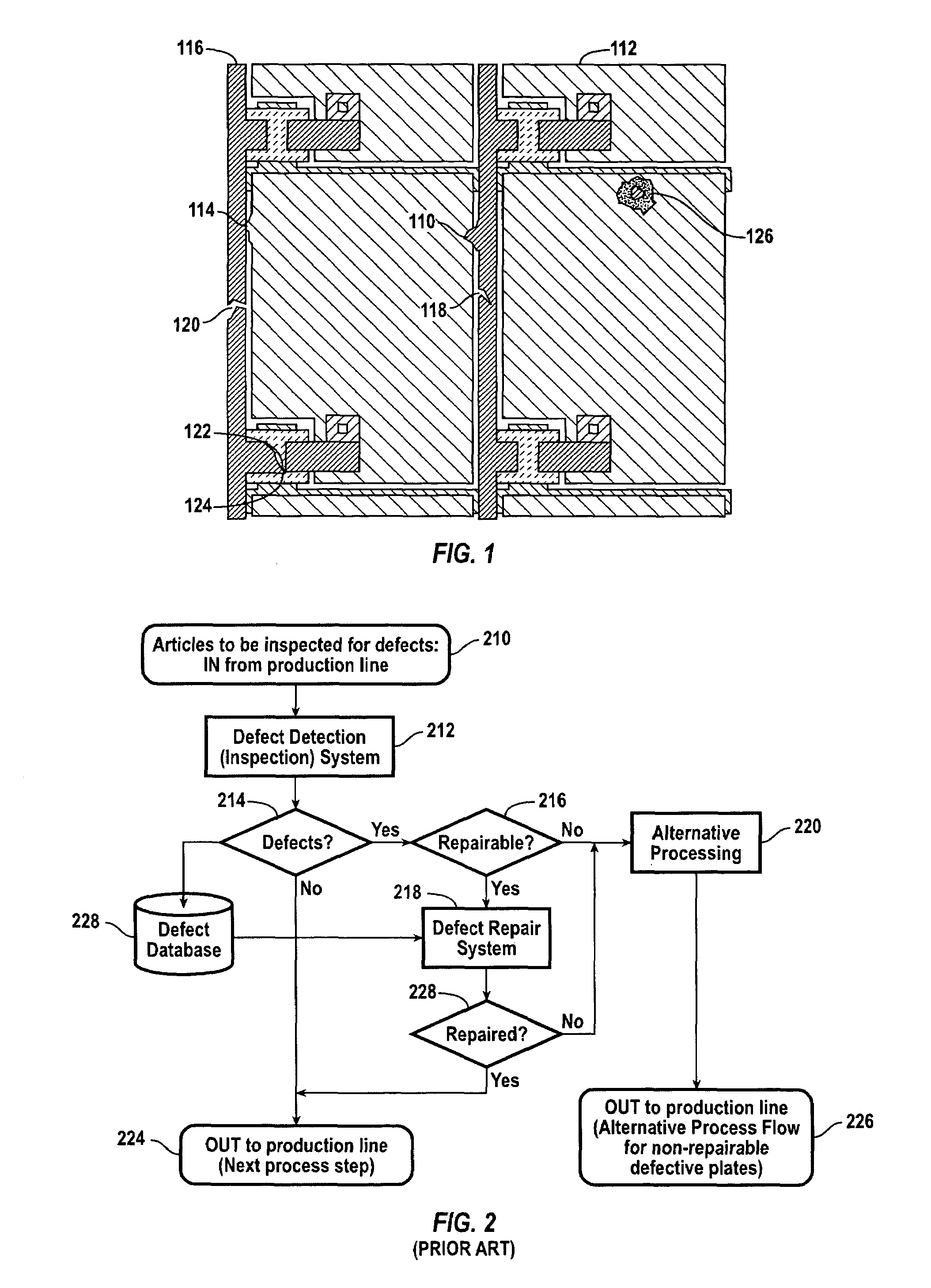
[0052]In an inspection system or in a group of systems consisting of inspection and repair equipment, a well defined process is used to determine how exactly the inspection and the subsequent optional repair operations will be performed. This process describes the roles of the sub-systems involved in the inspection and repair operations and the sequence of actions which will be performed on the article being inspected.

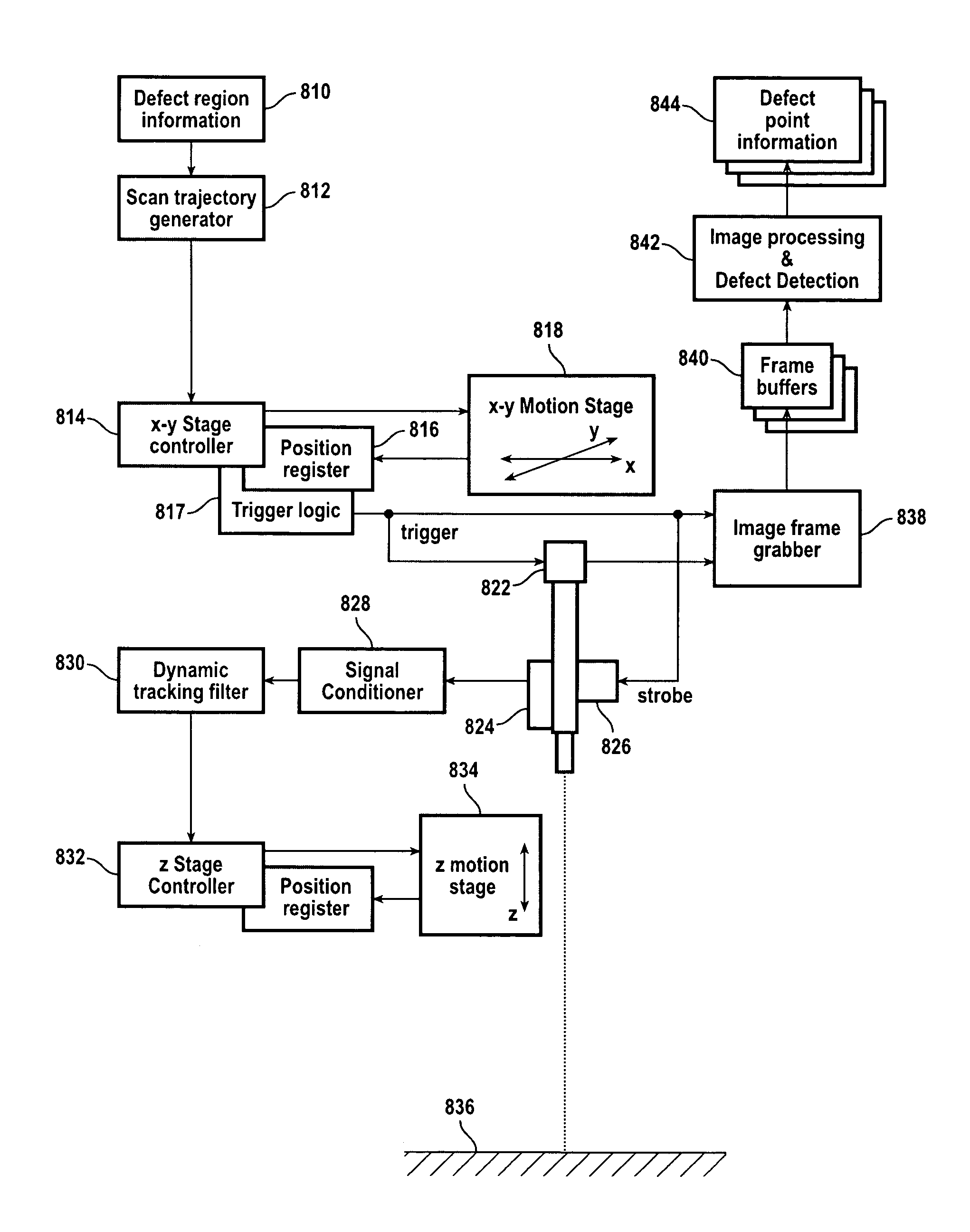
[0053]The present invention proposes to augment the instruments to add an improvement employing an AOI-on-demand sub-system.

[0054]The improved flow and added abilities to quickly identify defects with the added sub-system are considered to be a primary contribution of the present invention.

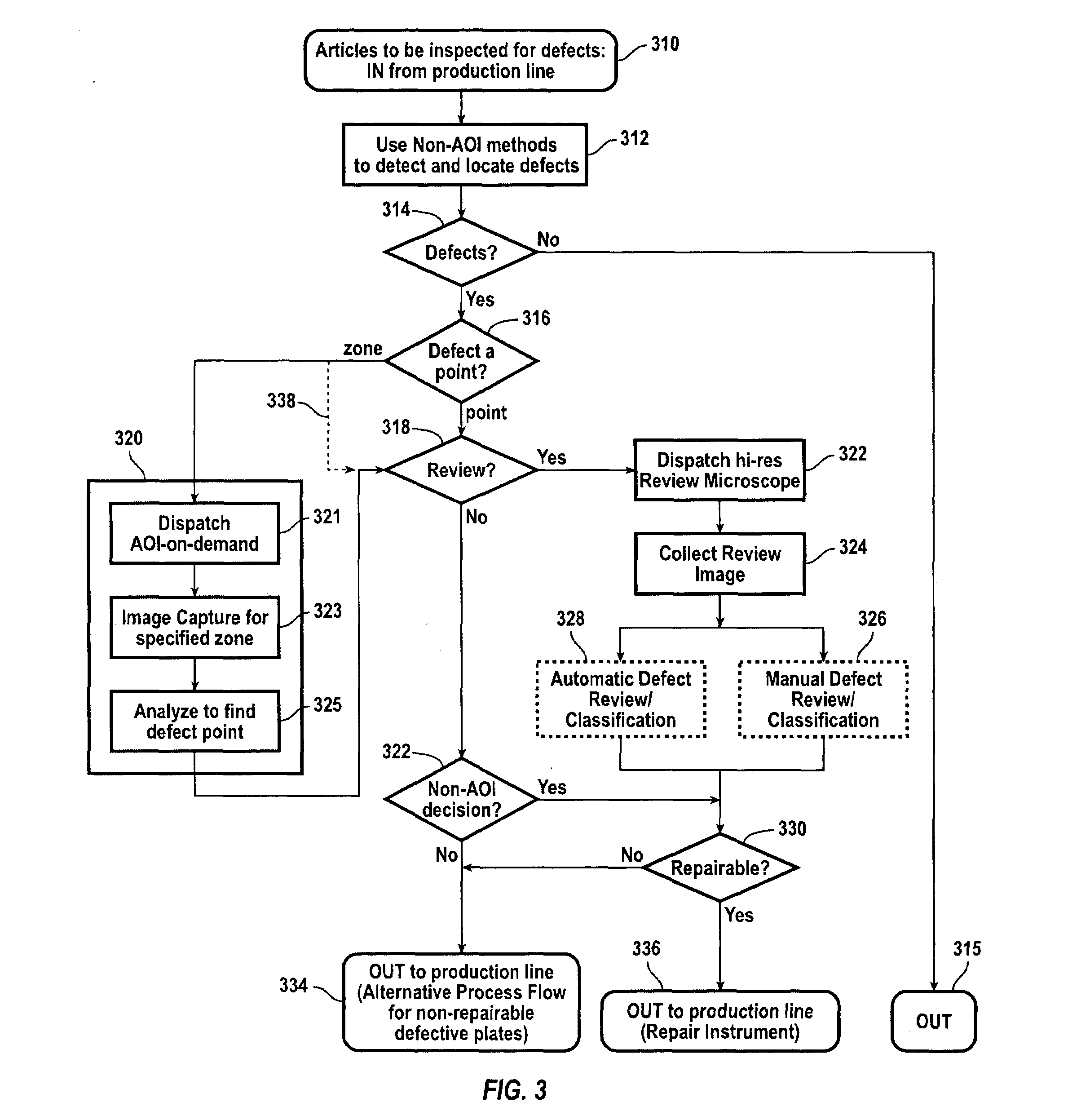
[0055]In FIG. 3, a specific embodiment of the AOI-on-demand process is presented where the new functionality is integrated into the inspection side of the process and into an inspection instrument. Articles subject to defect inspection are input (Step 310) to an inspection instrument...


PUM

PropertyMeasurementUnit
speedaaaaaaaaaa
speedaaaaaaaaaa
speedaaaaaaaaaa

Abstract

In an inspection system for electrical and electro-optical inspection of TFT-LCD panels, a fine resolution area imaging camera with a pulse illumination source disposed to scan the region and operative capture images of the region illuminated with pulses of short illumination and automatically maintained in focus while continuously scanning in order to resolve points of defects.

Description

CROSS-REFERENCES TO RELATED APPLICATIONS[0001]Not ApplicableSTATEMENT AS TO RIGHTS TO INVENTIONS MADE UNDER FEDERALLY SPONSORED RESEARCH OR DEVELOPMENT[0002]Not ApplicableBACKGROUND OF THE INVENTION[0003]This invention relates to the inspection of flat electronic circuit patterned media at various stages of production using electrical, electro-optical and optical techniques. More specifically, this invention relates to the automated electrical, electro-optical and optical inspection of flat electronic substrates, such as thin film transistor (TFT) arrays (the main component of the liquid crystal flat panel displays (LCD)). In particular, the focus is on the inspection of high density thin film transistor (TFT) liquid crystal display (LCD) panels, deposited on large sheets of glass.[0004]During the manufacturing of TFT LCD panels, large clear sheets of thin glass are used as a substrate for the deposition of various layers of materials to form electronic circuits that are intended to...

Claims


Application Information

Patent Timeline
Patent Type & Authority Patents(United States)
IPC IPC(8): G01N21/00G01N21/88G01N21/95
CPCG01N21/95G01N2021/9513G02F1/13
Inventor WEISS, ADAMSARANLI, AFSAR
Owner ORBOTECH LTD
Why Eureka
Try Eureka