High frame rate imaging system

a high frame rate, imaging system technology, applied in ultrasonic/sonic/infrasonic diagnostics, instruments, applications, etc., can solve the problems of large depth of field, large amount of power, complicated image reconstruction process, etc., and achieve high frame rate, high resolution, and high frame rate

Inactive Publication Date: 2009-02-05
UNIVERSITY OF TOLEDO
View PDF21 Cites 58 Cited by
  • Summary
  • Abstract
  • Description
  • Claims
  • Application Information

AI Technical Summary

Benefits of technology

[0010]In one aspect, there is provided a system for producing a high frame rate, high resolution and high contrast image The system generally can include: a) transmitting a group of signals of energy toward one or more objects to be imaged, the signals being weighted spatially on one or more transmitting apertures i) by square waves, or ii) by limited-diffraction beans; b) weighting or Fourier transforming receive signals spatially on one or more receiving apertures; c) reconstructing a two- or three-dimensional image data set from i) the transmitted signals, and, ii) the receive signals; and, d) reconstructing the image from the image data set of step c.
[0011]In another aspect, there is provided a system for producing a high frame rate, high resolution and high contrast velocity vector image of one or more objects where at least a part of one or more objects is moving. The system can generally include: a) transmitting two or more groups of signals of energy toward the one or more objects, the signals being weighted spatially on one or more transmitting apertures i) by square waves, or by limited diffraction beams; b) weighting or Fourier transforming receive signals spatially on one or more receiving apertures; c) reconstructing two- or three-dimensional image data sets from the groups of: i) the transmitted signals, and, ii) the receive signals; and; d) using the image data sets to reconstruct: i) a first set of flow velocity component images in a first direction, and ii) a second set of flow velocity component images in a second direction that is different from the first direction; and, e) reconstructing one or more velocity vectors image from the first and second sets of velocity component images.
[0012]In yet another aspect, there is provided a system for producing a high frame rate, high resolution and high contrast image of one or more objects. The system can be an apparatus that generally includes: 1) one or more devices configured to: a) transmit a group of signals of energy toward the one or more objects, the signals being weighted spatially on one or more transmitting apertures: i) by square-waves, or ii) by limited diffraction beams; and b) receive, and weight or Fourier transform receive signals spatially on one or more receiving apertures; 2) one or more devices configured to reconstruct a two- or three-dimensional image data set from the transmitted signals and the receive signals; and / or 3) one or more devices configured to reconstruct the image from the image data set.
[0013]In another aspect, there is provided a system for producing a high frame rate, high resolution and high contrast image comprising an array transducer probe operatively linked via an optical link to an imaging system. The array transducer probe can include one or more devices configured to transmit a group of signals of energy toward the one or more objects, the signals being weighted spatially on one or more transmitting apertures: i) by square-waves, or ii) by limited diffraction beams.
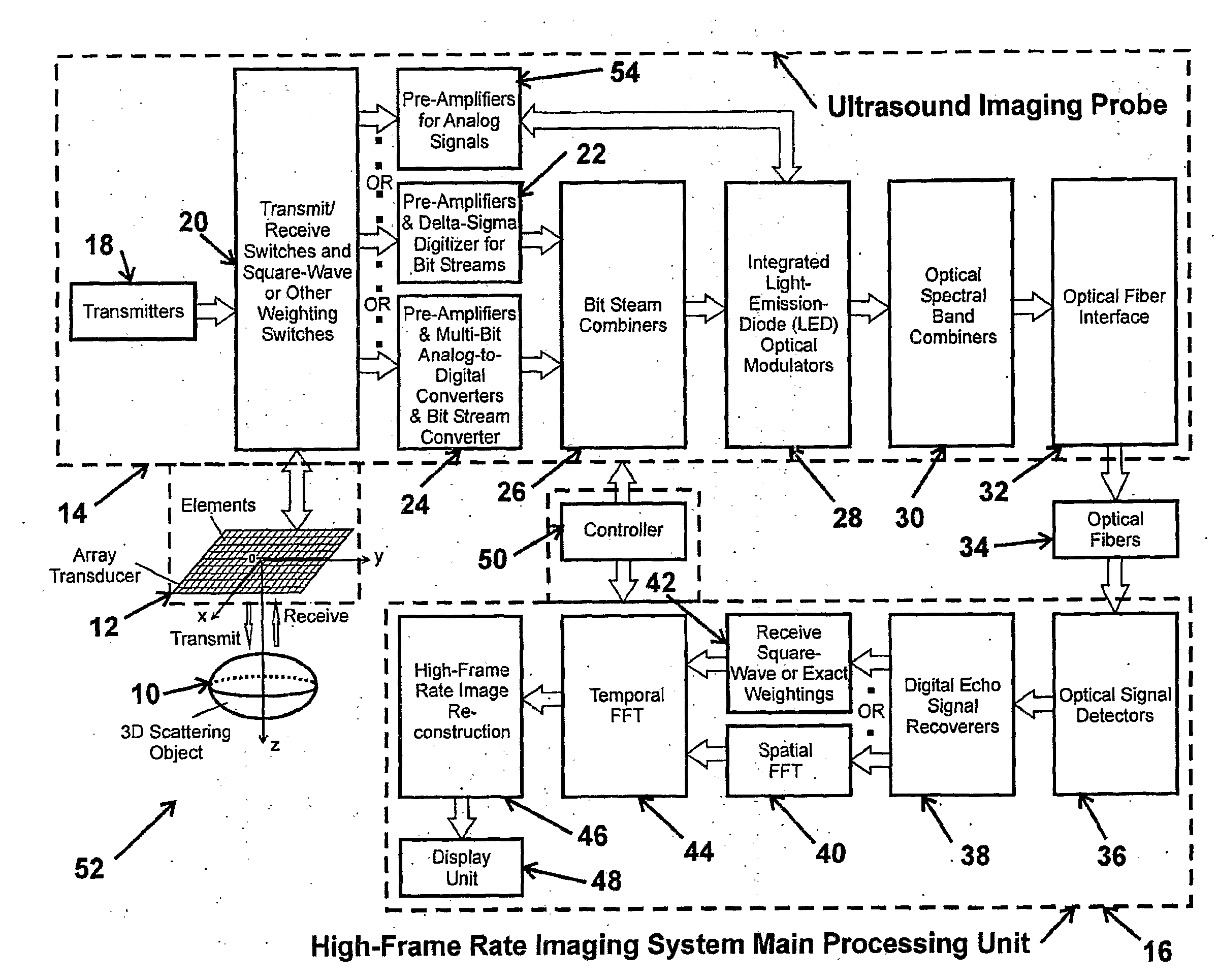
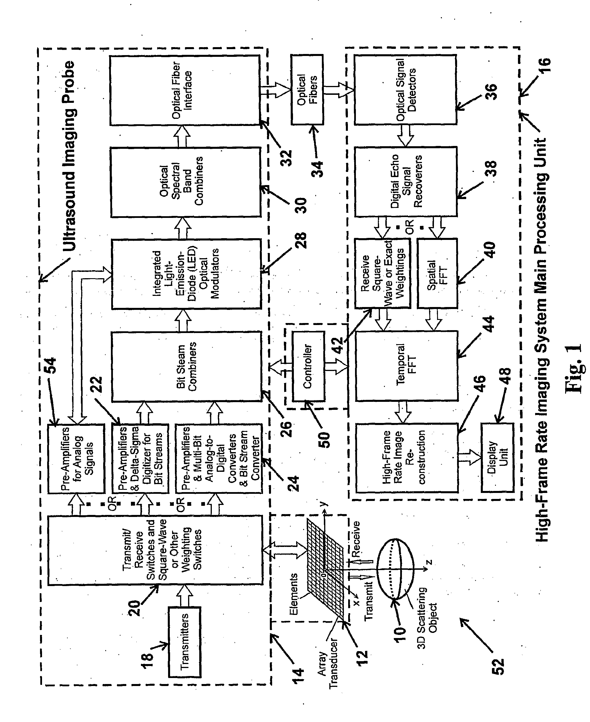
[0014]In still another aspect, there is provided a high frame rate imaging system comprising a high-speed optical link between an array transducer probe and an image reconstruction system. The optical link can include one or more of the following, alone or in combination: one or more multi-bit analog-to-digital converters or one or more delta-sigma digitizers configured to produce bit streams; one or more bit steam combiners configured to funnel multi-channel data into higher-speed bit steams with fewer channels; one or more light-emission-diodes (LED) or any suitable light-emission devices configured to convert electrical bit streams to optical signals; one or more optical spectral combiners configured to combine multi-channel optical signals; one or more optical fiber interface and fibers; and, one or more light detectors and circuits configured to recover original electrical receive echo data produced by the array transducer probe. The image reconstruction system can be configured to reconstruct multi-dimensional images through square-wave aperture weightings or spatial fast Fourier Transform FFT circuits. The system can further include a device to amplify signals from the array transducer probe.
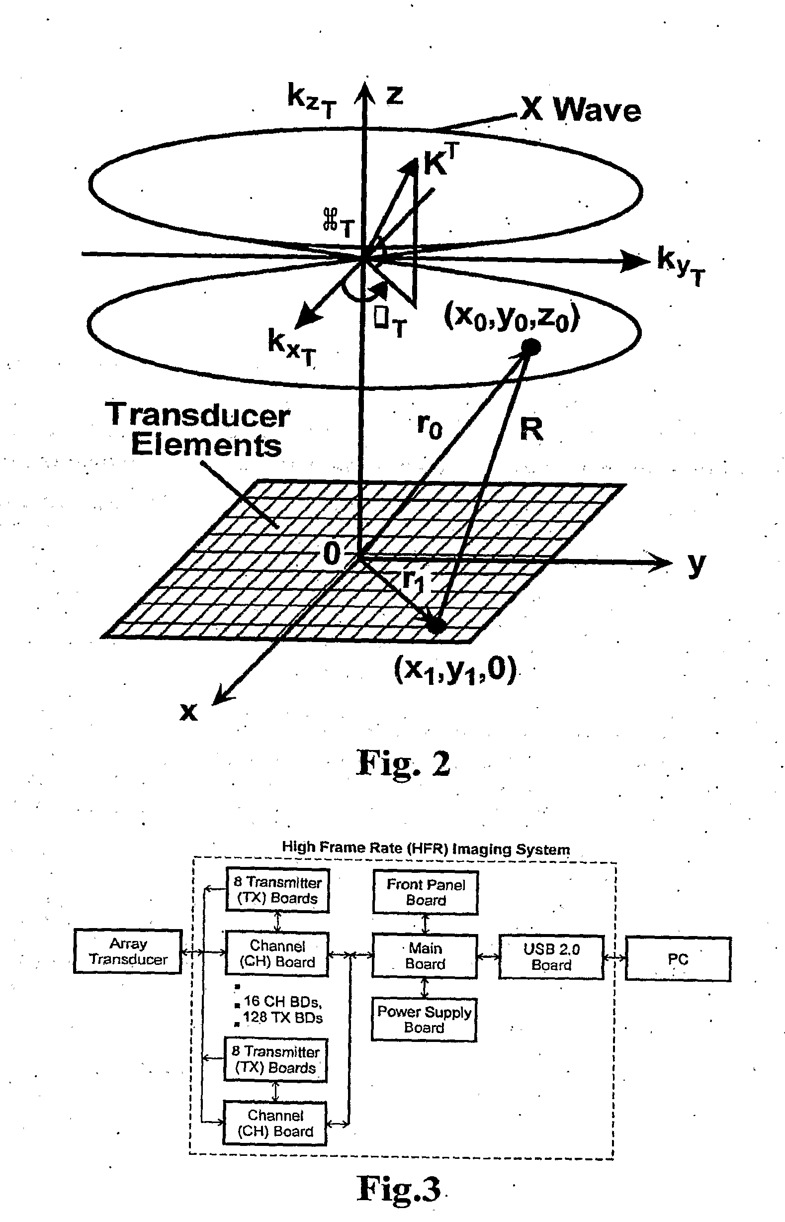
[0015]In yet another aspect, there is provided a high frame rate imaging system that can include one or more of the following, alone or in combination: a) a device capable of recording radio frequency (RF) data from one or more transducer elements for at least one heart cycle synchronized to an electrocardiogram (ECG)-signal at a desired frame rate determined by ultrasound propagation speeds and system timing overhead; b) at least one independent linear power transmitter and its associated fast transmit / receive (T / R) switch for each transducer element; and, c) a device capable of storing the acquired RF data and transferring the stored data to a computer for one or more of signal processing and image reconstruction.

Problems solved by technology

In practice, when these beams are produced with finite aperture and energy, they have a large depth of field.
Although the extended high-frame rate imaging method has many advantages, an imaging system to implement this method still has many challenges, such as: i) the imaging system is complicated and requires a large amount of power to operate and thus is difficult to be integrated to a transducer probe that a physician can hold to move freely around a patient; ii) the amount of data acquired by an array transducer, especially, an array of a large number of elements such as two-dimensional arrays, is huge and thus would be difficult to be transferred to a separate imaging system through fewer cables; iii) there would be too many cables to send transmit signals to individual transducer elements to produce ultrasound for an array with a large number elements; and iv) the image reconstruction process is complicated and requires many circuits.

Method used


Image

  • High frame rate imaging system
  • High frame rate imaging system
  • High frame rate imaging system

Examples


Embodiment Construction

)

[0037]I. High-Frame Rate Imaging System and Square-Wave Aperture Weightings in Transmissions

[0038]I.A. Theoretical Preliminaries

[0039]To understand the method of limited-diffraction array beam imaging with square-wave aperture weightings, it is helpful to summarize briefly the extended HFR imaging method and relate it to the X wave theory [4]-[8] for completeness. From the theory, it is shown that the relationship that the limited-diffraction array beam aperture weightings [24]-[26] on echo signals are identical to the 2D Fourier transform of the signals on the same transducer aperture can be generalized to an arbitrary transmit beam. The theory also makes it clear that with the square-wave aperture weightings, the transmission scheme of an imager could be simplified from that of the traditional D&S method [38], i.e., in principle, only one or two transmitters are needed to implement a 3D ultrasound imaging system. In addition, the square-wave aperture-weighting concept can also be...


PUM


Abstract

A system for producing an image using an imaging system includes a) transmitting at least one signal of energy toward an object to be imaged by using two transmitters having the same output amplitude but of an opposite sign, or by using one transmitter to perform the task; b) exciting at least one transducer element to produce limited-diffraction array beams or their square-wave approximations with two levels of quantitations for both sine and cosine functions, c) weighting the received signals spatially with limited-diffraction array beams, their square-wave approximations, or spatial Fourier transform, and d) digitizing and then transferring received signals through high-speed optical fibers to a system for image reconstructions.

Description

CROSS REFERENCE TO RELATED APPLICATIONS AND SPONSORED RESEARCH[0001]This application claims the benefit of U.S. Provisional Application Nos. 60 / 762,326 filed Jan. 26, 2006, and 60 / 818,273, filed Sep. 29, 2006, the disclosures of which are expressly incorporated herein by reference.[0002]This invention was made partly with government support under Grant No. R01 HL60301 awarded by the National Institute of Health. The government has certain rights in this invention.FIELD OF THE INVENTION[0003]A novel high-frame rate (HFR) imaging system that uses a square-wave aperture weighting imaging method to produce multi-dimensional images.BACKGROUND OF THE INVENTION[0004]One of the limited-diffraction beams, the Bessel beam, was first studied theoretically by Stratton [1] and then experimentally by Durnin et al [2]-[3]. In 1991, new families of limited-diffraction beams such as X waves were discovered [4]-[8]. X waves are multiple-frequency waves and have the same phase and group velocity. Theo...

Claims


Application Information

Patent Timeline
Patent Type & Authority Applications(United States)
IPC IPC(8): A61B8/00G06K9/00
CPCG01S7/52046G01S7/52074G01S15/8977G01S15/8909G01S7/5208
Inventor LU, JIAN-YU
Owner UNIVERSITY OF TOLEDO
Why Eureka
Try Eureka