

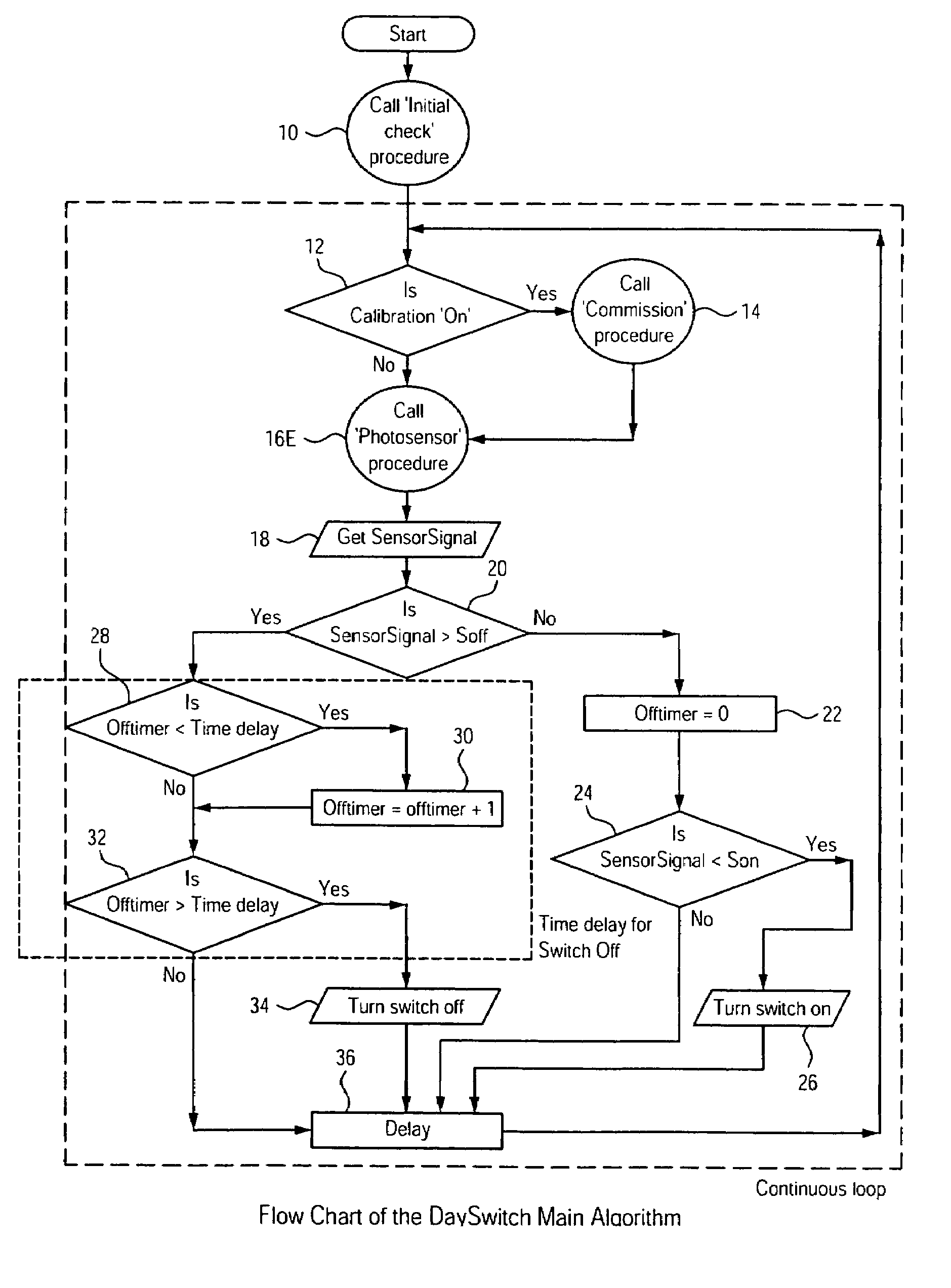
Self-commissioning daylight switching system
a self-commissioning, switching system technology, applied in lighting control systems, lighting devices, electrical devices, etc., can solve the problems of difficult illumination control, ineffective daylight dimming systems, and reluctant installation of lighting control systems that dim or switch electrical lighting fixtures, so as to reduce the peak load requirement, improve building end-use efficiency, and reduce lighting energy
- Summary
- Abstract
- Description
- Claims
- Application Information
AI Technical Summary
Benefits of technology
Problems solved by technology
Method used
Image

Examples
Embodiment Construction
[0052]Although the invention is illustrated and described herein with reference to specific embodiments, the invention is not intended to be limited to the details shown. Rather, various modifications may be made in the details within the scope and range of equivalents of the claims and without departing from the invention.
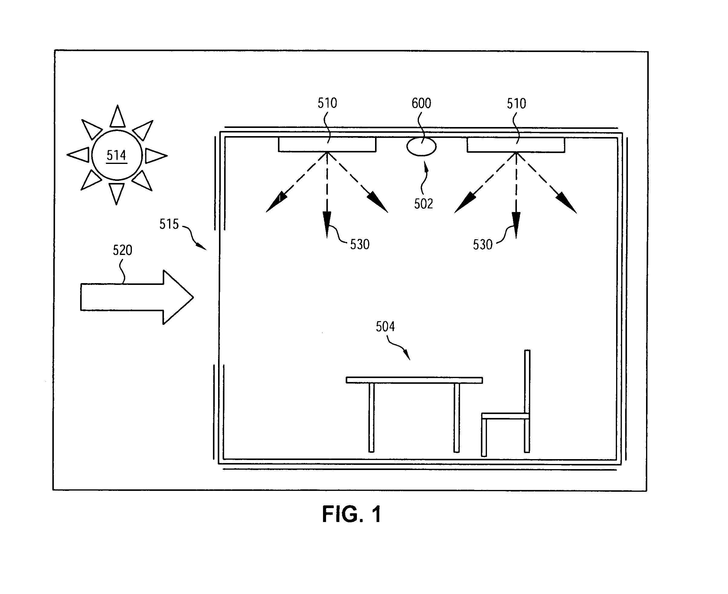
[0053]Referring now to the drawing, in which like reference numbers refer to like elements throughout the various figures that comprise the drawing, FIG. 1 shows a typical work space 501. Typical work space 501 has windows 515 which allow daylight 520 from the sun 514 and reflected daylight from the sky and ground to enter the work space 501. This daylight 520 could be used to replace some or all of the electric light 530 provided by one or more electrical lighting fixtures 510 or luminaires to provide illumination of a task location 504 in the work space 501. To control the amount of illumination provided by lighting fixtures 510, a sensor module 600 may be incor...
PUM
 Abstract
Description
Claims
Application Information