Pivotal device

a pivotal device and contact surface technology, applied in the direction of portable computer details, instruments, casings of electrical apparatuses/cabinets/drawers, etc., can solve the problems of pivotal device wear and tear, enlarged overall thickness of electronic device, and wear and tear on the contact surface between two adjacent devices, so as to prevent the occurrence of wear and tear and simple structural design

Active Publication Date: 2006-05-23
ASUSTEK COMPUTER INC
View PDF9 Cites 39 Cited by
  • Summary
  • Abstract
  • Description
  • Claims
  • Application Information

AI Technical Summary

Benefits of technology

[0006]It is therefore an object of the invention to provide a pivotal device capable of making rotary and forward / backward movements. By means of a simple structural design, the pivotal device is able to move relatively forward or backward when rotates, preventing the occurrence of wear and tear on the surface of the two adjacent parts of the electronic device which are pivotally connected via the pivotal device, leaving only a small clearance between the two adjacent parts.

Problems solved by technology

However, when a part of the electronic device is rotated against another part thereof, wear and tear on the contact surface between two adjacent devices pivotally connected by a pivotal device would occur.
The above approach may have solved the problem at one hand, but at the other hand, the overall thickness of the electronic device is enlarged and the external aesthetics is deteriorated.

Method used


Image

  • Pivotal device
  • Pivotal device
  • Pivotal device

Examples


embodiment one

PREFERRED EMBODIMENT ONE

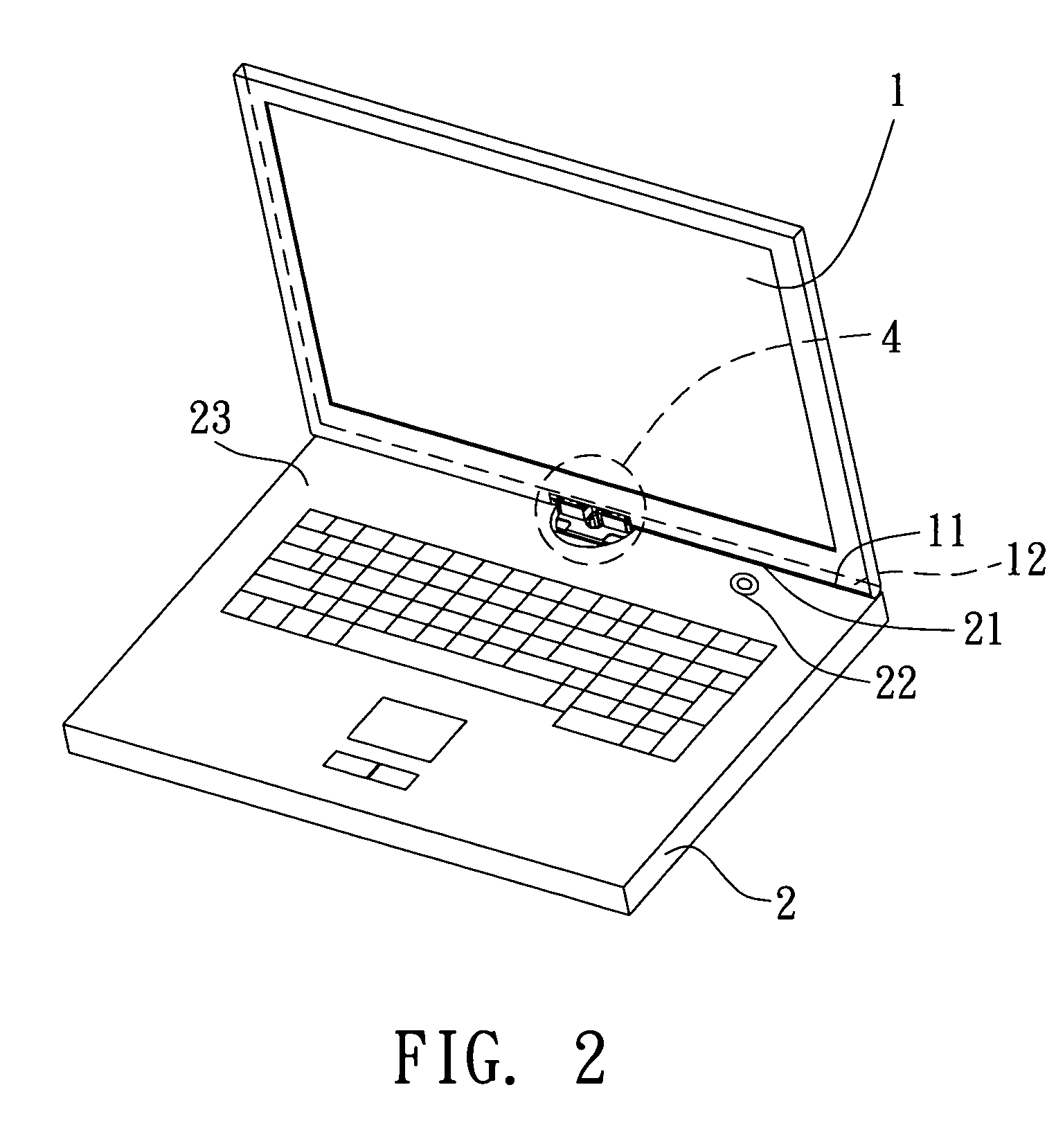
[0027]Referring to FIG. 2, pivotal device 4 connects a first connecting side 11 of a monitor section 1 to a second connecting side 21 of a mainframe section 2 so that the monitor section 1 may rotate against or move towards / away from the mainframe section 2.

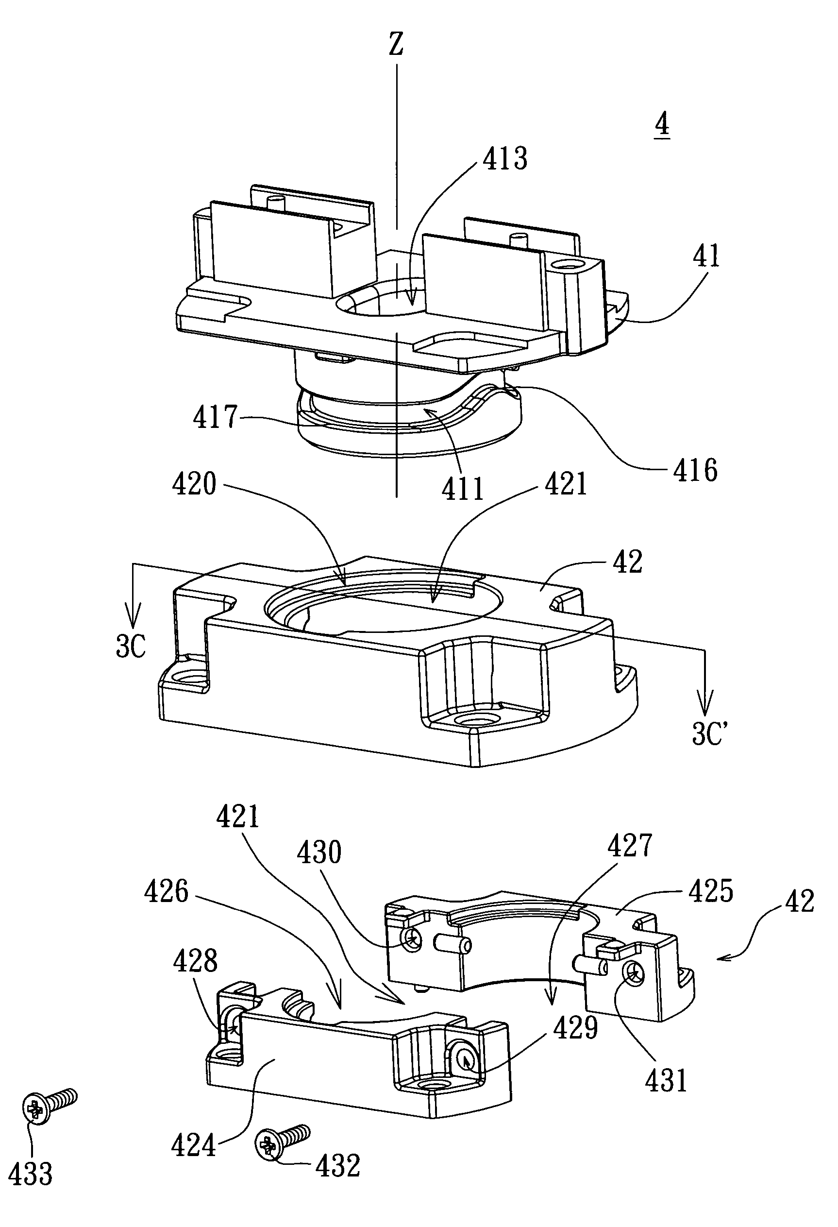
[0028]Referring to FIG. 2, FIG. 3A, FIG. 3B and FIG. 3C at the same time. Pivotal device 4 includes a rotary spindle 41 and a holder 42. The rotary spindle 41 is fixed onto the first connecting side 11 of the monitor 1, wherein the lateral side of the rotary spindle 41 has a sliding track 411 while the axial direction Z of the rotary spindle 41 has a first run-through hole 413 which the electrical wire 415 connecting the monitor section 1 and the mainframe section 2 runs through. The holder 42, which has a second run-through hole 421 for pivotally connecting the rotary spindle 41, is fixed onto the second connecting side 21 of the mainframe section 2. As shown in FIG. 3C, the second run-through hole 421 ha...

embodiment two

PREFERRED EMBODIMENT TWO

[0035]Referring to FIG. 12, a decomposition of pivotal device 4′ according to preferred embodiment two of the invention. As shown in FIG. 12, the pivotal device 4′ includes a rotary spindle 41′, a first holder 424′ and a second holder 425′. The first holder 424′ and the second holder 425′ are semi-circular and together form a circular holder 42′. Another difference between the present and the previous preferred embodiments is that the dispositions of the first protrusion 422′, the second protrusion 423′ and the sliding track 411′ are different. Like what is shown in FIG. 6 of preferred embodiment one: the rotary spindle 41′ is fixed onto the first connecting side 11 of the monitor section 1; the lateral side of the rotary spindle 41′ has a first protrusion 422′ and a second protrusion 423′; a first run-through hole 413′ is disposed along the axial direction Z′ of the rotary spindle 41′ for an electrical wire 415 connecting the monitor section 1 and the mainfr...

embodiment three

PREFERRED EMBODIMENT THREE

[0036]Referring to both FIG. 13A and FIG. 13B. FIG. 13A is a decomposition of pivotal device 4″ according to preferred embodiment three of the invention. The pivotal device 4′ includes a rotary spindle 41″ and a first stand 42″. The difference between the present preferred embodiment and preferred embodiment one is that preferred embodiment three uses the sharp ends of screws 422″ and 423″ to replace the first protrusion 422 and the second protrusion 423 shown in FIG. 3C of preferred embodiment one. Like what is shown in FIG. 6 of preferred embodiment one: the rotary spindle 41″ is fixed onto the first connecting side 11 of the monitor section 1 (shown in FIG. 13A and FIG. 6); the lateral side of the rotary spindle 41″ has a sliding track 411″; a first run-through hole 413″ is disposed along the axial direction Z″ of the rotary spindle 41″ for an electrical wire 415 connecting the monitor section 1 and the mainframe section 2 to run through. The holder 42″ ...


PUM


Abstract

A pivotal device which is fixed onto a first body and a second body and enables the first body to make rotary and upward / downward movements against the second body is provided. The pivotal device includes a rotary spindle and a holder. The rotary spindle which has a sliding track disposed on the lateral side thereof is fixed onto the first body. The holder, which is fixed onto the second holder, has a second run-through hole for pivotally connecting the rotary spindle with at least a protrusion section which is inlaid into the sliding track being disposed at the second run-through hole. When the rotary spindle rotates, the protrusion section will slide along the sliding track enabling the rotary spindle to move closer to or farther from the holder.

Description

[0001]This application claims the benefit of Taiwan application Serial No. 92132090, filed Nov. 14, 2003, the subject matter of which is incorporated herein by reference.BACKGROUND OF THE INVENTION[0002]1. Field of the Invention[0003]The invention relates in general to a pivotal device, and more particularly to a pivotal device capable of making rotary and forward / backward movements.[0004]2. Description of the Related Art[0005]The press button or the keyboard installed on the surface of an electronic device is normally designed to be higher than the surface thereof to facilitate the user's operation. However, when a part of the electronic device is rotated against another part thereof, wear and tear on the contact surface between two adjacent devices pivotally connected by a pivotal device would occur. The prior art in solving the problem is to leave a big clearance between the two adjacent parts pivotally connected together. The above approach may have solved the problem at one han...

Claims


Application Information

Patent Timeline
Patent Type & Authority Patents(United States)
IPC IPC(8): E05D3/10E05D3/02E05D11/00G06F1/16
CPCG06F1/1681G06F1/1683G06F1/162E05D3/022E05D3/10E05D11/0081E05Y2900/606Y10T16/5398Y10T16/5472
Inventor HUANG, TIEN-AN
Owner ASUSTEK COMPUTER INC
Why Eureka
Try Eureka