Venting device

a technology of ventilation device and valve body, which is applied in the direction of functional valve types, machines/engines, liquid fuel feeders, etc., can solve the problem of high installation cost, and achieve the effect of low structural cost and simple manner

Inactive Publication Date: 2006-05-23
SIEMENS AG
View PDF17 Cites 10 Cited by
  • Summary
  • Abstract
  • Description
  • Claims
  • Application Information

AI Technical Summary

Benefits of technology

[0006]This design enables the venting device according to the invention to be fitted together with the venting line on one of the shell parts. When the second shell part is mounted upon it, the free end of the venting line is moved into a position in which the connection of the shell parts is not obstructed. The venting device according to the invention can thereby be higher than the fuel tank. A safety distance between the venting line and the upper wall of the fuel tank is therefore not required. The venting line is therefore arranged in the upper region of the fuel tank even if the venting line and the fuel tank have tolerances. This enables even a fuel tank which is filled with fuel to be reliably vented.
[0009]Sloshing of fuel into the venting device according to the invention can be avoided in a simple manner if the venting line has a valve at its free end.
[0012]According to another advantageous development of the invention, manufacturing costs of the venting line are reduced if the movable section is designed to be flexible and tapers obliquely to the upper wall of the fuel tank. In this case, the movable section may be designed, for example, as a corrugated pipe.
[0013]According to another advantageous development of the invention, the movable section can be reliably sealed with a particularly low constructional outlay if it has an expansion bellows or a corrugated hose.
[0017]According to another advantageous development of the invention, the installation of the movable section of the venting line turns out to be particularly simple if one of the telescopic pipes has an elongated recess and the other of the telescopic pipes has a latching hook which penetrates the recess and is short in relation thereto.
[0018]According to another advantageous development of the invention, the control of the valve requires a particularly low outlay if the valve has a float.

Problems solved by technology

However, this requires a high outlay on installation.

Method used


Image

  • Venting device
  • Venting device
  • Venting device

Examples


Embodiment Construction

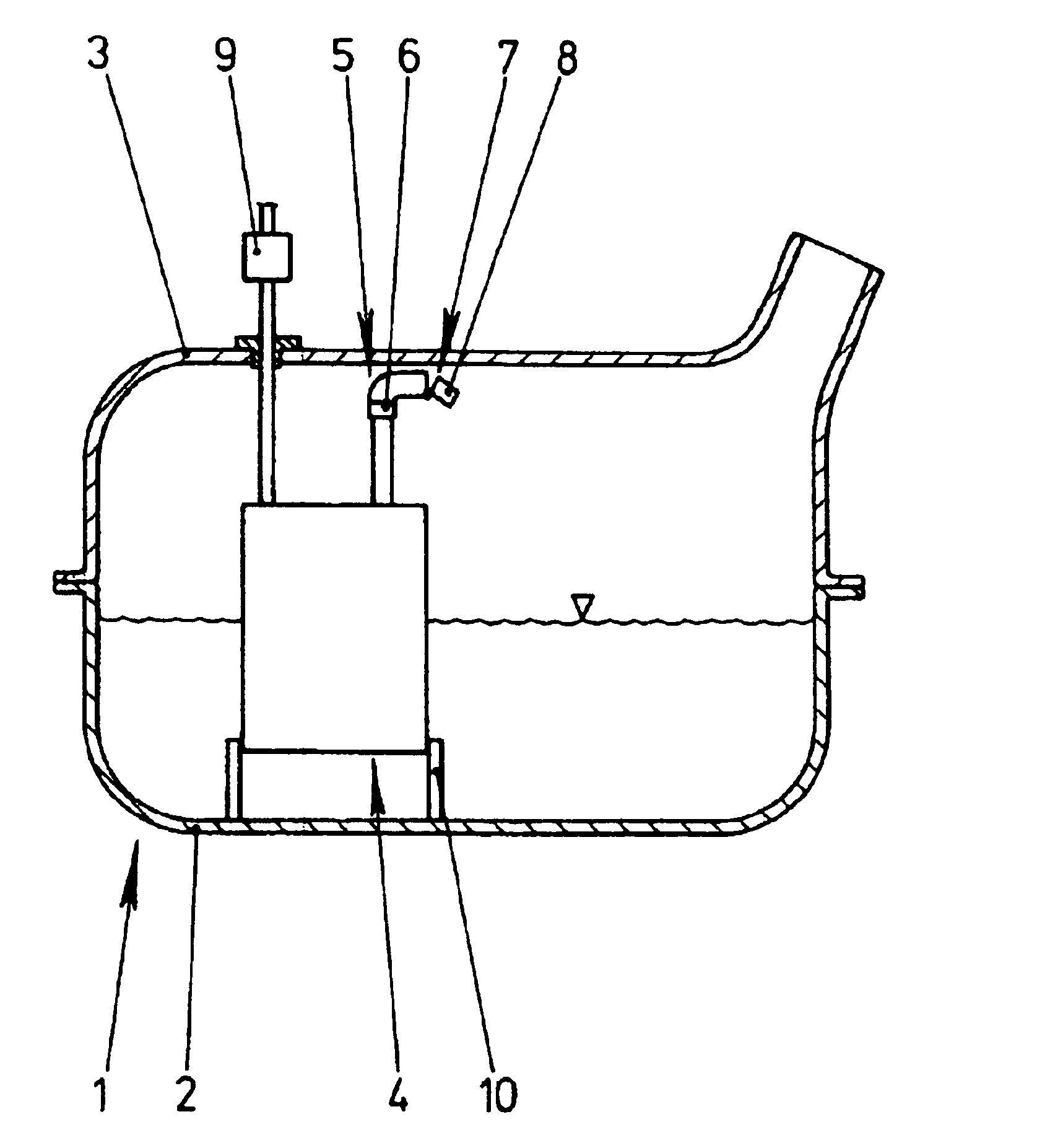
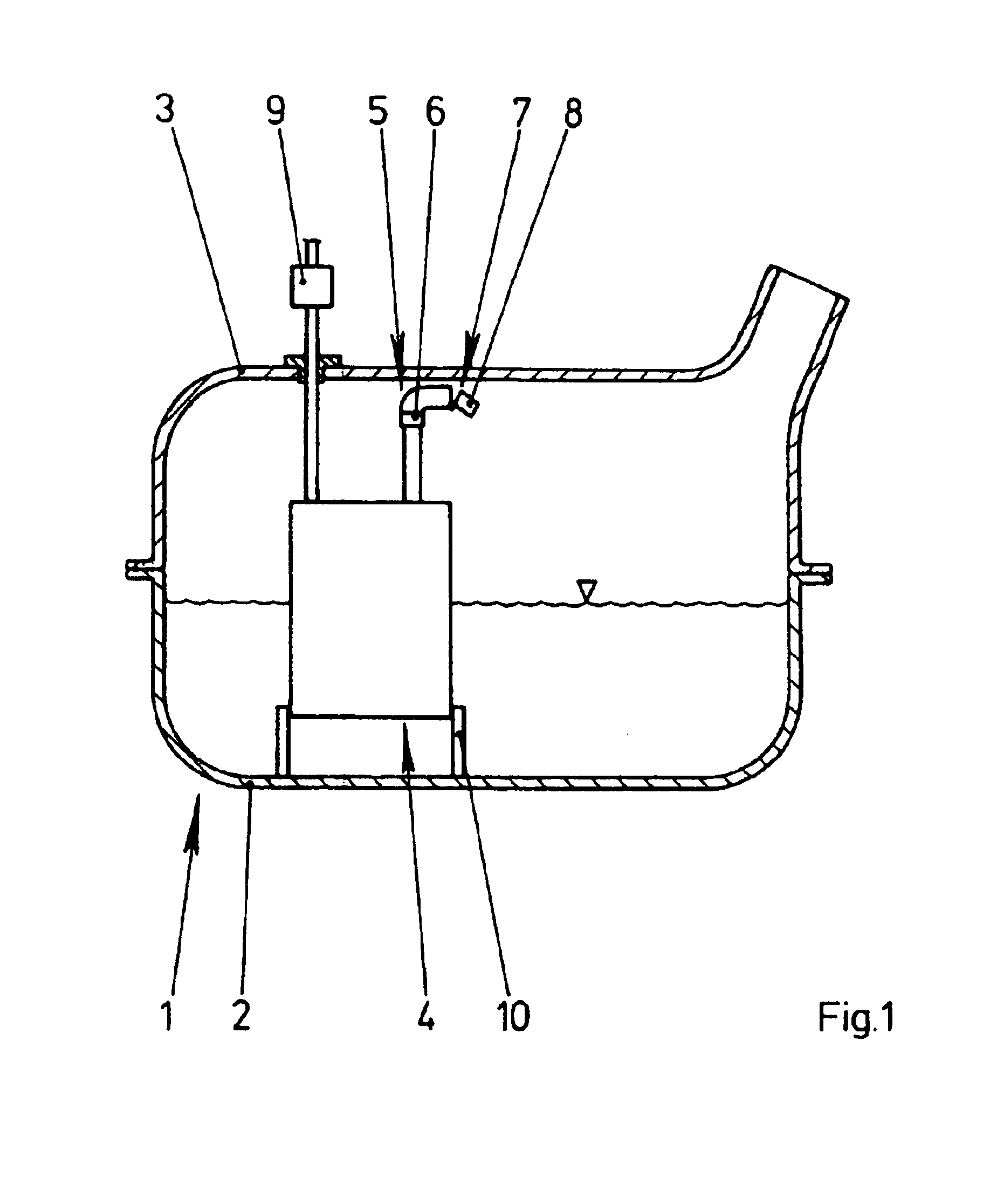
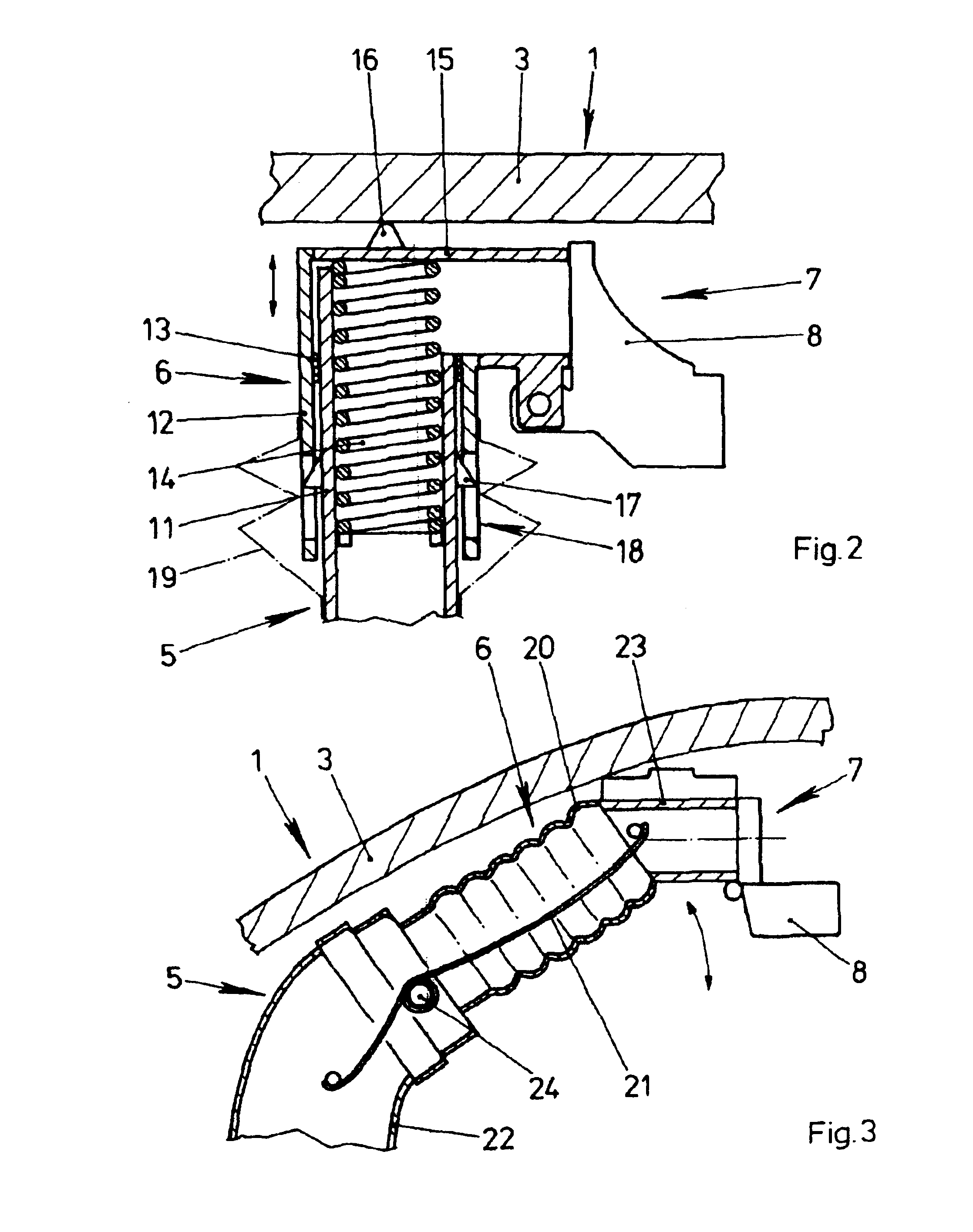
[0023]FIG. 1 shows a fuel tank 1 having two shell parts 2, 3. FIG. 1 furthermore shows a venting device 4 having a venting line 5 guided in the upper region of the fuel tank 1. The free end of the venting line 5 has a movable section 6 and is supported on the upper wall of the fuel tank 1. In addition, the free end of the venting line 5 holds a valve 7 with a pivotably mounted float 8. This prevents fuel from being able to slosh into the venting device 4. A further line is connected to an activated carbon filter 9 arranged outside the fuel tank 1. The lower of the shell parts 2 holds a mount 10 for the venting device 4. For installation purposes, the venting device 4 is fitted in the mount 10 and then the upper of the shell parts 3 is placed onto the lower shell part 2 and sealingly connected to the latter at the edges.

[0024]A condenser, for example, can be arranged within the venting device 4 and gases flowing in via the venting line 5 are cooled in it, so that the hydrocarbons con...


PUM


Abstract

In a venting device for a fuel tank (1), a venting line (5) has a movable section (6) and a spring element (14). The free end of the venting line (5) is prestressed against an upper wall of the fuel tank (1). This ensures that a valve (7) which is arranged at the free end of the venting line (5) is always arranged in the vicinity of the upper wall of the fuel tank (1).

Description

BACKGROUND OF THE INVENTION[0001]The invention relates to a venting device for a fuel tank having a venting line which is arranged in the fuel tank and is guided as far as the upper wall.[0002]Venting devices of this type are frequently used in modern fuel tanks and are known from practice. The venting line is frequently connected to a bubble tank of the venting device. In particular in the case of fuel tanks manufactured from shell parts, the bubble tank is generally fitted together with other components on the lower of the shell parts. The shell parts of the fuel tank are then connected to one another.[0003]The venting line here requires a safety distance from the upper wall, so that the shell parts of the fuel tank can be reliably connected to one another. The safety distance has to compensate for the tolerances which arise through the manufacturing of the venting device and of the shell parts and the installation of the venting line. In addition, the wall of the fuel tank, after...

Claims


Application Information

Patent Timeline
Patent Type & Authority Patents(United States)
IPC IPC(8): F02M33/02F16K24/02B60K15/035
CPCB60K15/035B60K15/03519B60K15/03504B60K2015/03514Y10T137/86324Y10T137/86348Y10T137/3099Y10T137/8626
Inventor REITER, FRANKSCHONERT, OLIVER
Owner SIEMENS AG
Why Eureka
Try Eureka