Breather of a hydraulic or electrohydraulic control device

a hydraulic or electrohydraulic control and ventilation device technology, applied in separation processes, liquid degasification, transportation and packaging, etc., can solve the problems of air entrapped in the hydraulic system, general adverse effect of the control and regulating behavior of the hydraulic system, and undesired loss of system performan

Inactive Publication Date: 2015-06-30
ZF FRIEDRICHSHAFEN AG
View PDF20 Cites 0 Cited by
  • Summary
  • Abstract
  • Description
  • Claims
  • Application Information

AI Technical Summary

Benefits of technology

[0008]The purpose of the present invention is to provide a venting device for a hydraulic or electro-hydraulic control unit by means of which a space in the control unit that contains oil can be reliably vented to the outside without significant oil leakage and without air from the outside being able to make its way back into the space in the control unit to be vented.
[0011]In a further development of the invention it is proposed to provide additional design means in the hydraulic or electro-hydraulic control unit, in the area of the oil feed to the housing bore, which prevent the oil column from draining out of the housing bore when the control unit is not operating. This can ensure that at no time can air from outside be drawn into the hydraulic system of the control unit via the venting device.

Problems solved by technology

As is known, air entrapped in a hydraulic system generally has an adverse effect on the control and regulating behavior of the hydraulic system.
Although such a device reliably vents the hydraulic space concerned, this takes place at the cost of a continual oil leak which has to be allowed for in the design of the oil supply to the control unit and generally leads to some undesired loss of performance in the system.
Besides, in some operating situations it can happen that air from the outside is drawn back into the hydraulic control unit by way of the venting diaphragm.

Method used


Image

  • Breather of a hydraulic or electrohydraulic control device
  • Breather of a hydraulic or electrohydraulic control device

Examples


Embodiment Construction

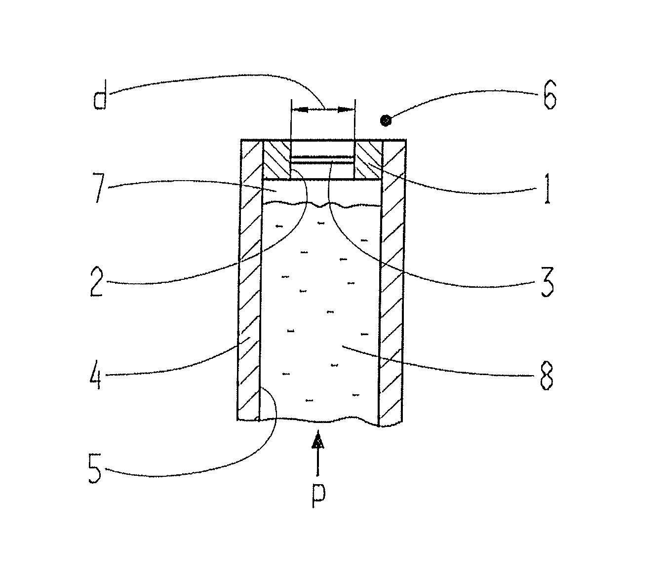
[0016]The invention is based on the recognition that PTFE (polytetrafluoroethylene) membranes known from the prior art conform to a mathematical venting curve. FIG. 1 shows a typical venting curve A, with an oil pressure p that acts on the PTFE membrane plotted along the abscissa and a volume flow Q passing through the PTFE membrane plotted along the ordinate of the coordinate system. It can be seen clearly that a PTFE membrane acted upon by pressure is at least largely impermeable to both air and oil until a discrete pressure threshold—in the material example shown, approximately 0.5 bar—has been reached, and only above that pressure threshold can air pass through the membrane in larger amounts.

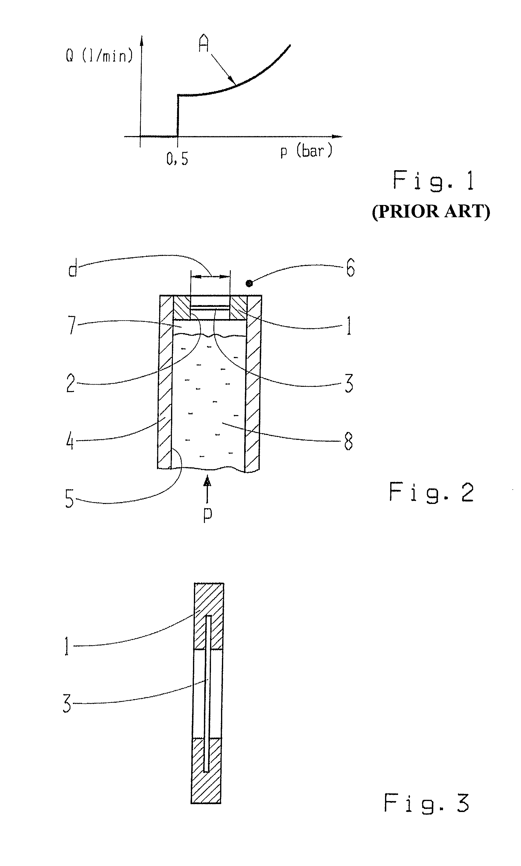
[0017]Now, if in accordance with the invention such a membrane is used to close off a space or a housing bore of the housing of a hydraulic or electro-hydraulic control unit, which space can be filled with oil from the control unit, then up to the discrete pressure threshold typical for the ...


PUM

PropertyMeasurementUnit
pressureaaaaaaaaaa
flow rateaaaaaaaaaa
leakage flow rateaaaaaaaaaa

Abstract

A venting device for a hydraulic control unit, designed as a diaphragm in a bore in the control unit, so that collected air can escape, via the diaphragm, to outside the housing. A membrane, which is permeable to air and oil when under pressure, closes the diaphragm bore with respect to the outside. The housing bore and the diaphragm form an inside space that can be vented, via the membrane. The inside space being delimited, during operation, by the diaphragm and an oil column which passes from the control unit into the housing bore and is continually maintained at a defined pressure at which oil, in the housing bore, either does not pass through the membrane or only a minute amount passes therethrough. The oil column remains in the housing bore so that only air, contained in the oil, is vented to the outside without any air being drawn into the control unit from outside.

Description

[0001]This application claims priority from German patent application serial no. 10 2012 214 388.2 filed Aug. 13, 2012.FIELD OF THE INVENTION[0002]The invention concerns a venting device for a hydraulic or electro-hydraulic control unit.BACKGROUND OF THE INVENTION[0003]As is known, air entrapped in a hydraulic system generally has an adverse effect on the control and regulating behavior of the hydraulic system. This air can on the one hand be so-termed primary air, which enters the hydraulic system during the assembly of its components and which, in the ready-assembled unit, undesirably remains trapped at some point or another. On the other hand, air can also make its way into the hydraulic system at a later time, during the operation of the ready-assembled unit.[0004]From DE 19717043 C2 it is known that water present in the hydraulic fluid of a hydraulic unit and gases dissolved in the hydraulic fluid of a hydraulic unit can be separated off by pervaporation methods. In this case t...

Claims


Application Information

Patent Timeline
Patent Type & Authority Patents(United States)
IPC IPC(8): F15B21/04B01D19/00F15B21/044
CPCF15B21/044Y10T137/3087
Inventor HAASER, NORBERT
Owner ZF FRIEDRICHSHAFEN AG
Why Eureka
Try Eureka