Power tool

a technology of power tools and components, applied in the field of power tools, can solve the problems of large rebound force produced by the anvil upon impingement the housing, damage to the speed reduction mechanism portion, etc., and achieve the effect of improving durability

Inactive Publication Date: 2006-05-23
KOKI HLDG CO LTD
View PDF29 Cites 52 Cited by
  • Summary
  • Abstract
  • Description
  • Claims
  • Application Information

AI Technical Summary

Benefits of technology

[0007]This invention seeks to provide a power tool of a long lifetime which is enhanced in durability by overcoming the above problems and by damping a rotational impact force acting on a speed reduction mechanism portion.

Problems solved by technology

However, in the case of driving the screw into a hard wooden material or in the case of fastening a bolt to an iron plate, the rebounding force, produced by the anvil upon impingement, was very large, so that the hammer was moved back until it impinged on the stopper provided at the spindle.
Therefore, even when the locking effect acted on the spindle, a large load (rotational impact force) was exerted on the gear portions of the speed reduction mechanism portion, provided between the motor and the spindle, since the pinion of the motor was rotating, and as a result there was encountered a problem that the speed reduction mechanism portion and the housing, holding this speed reduction mechanism portion, were damaged.
And besides, a locking effect acted on the spindle when the hammer claw impinged on the anvil claw, and therefore there was encountered a problem that the speed reduction mechanism portion and the housing, holding this speed reduction mechanism portion, were damaged.

Method used


Image

  • Power tool
  • Power tool
  • Power tool

Examples


first embodiment

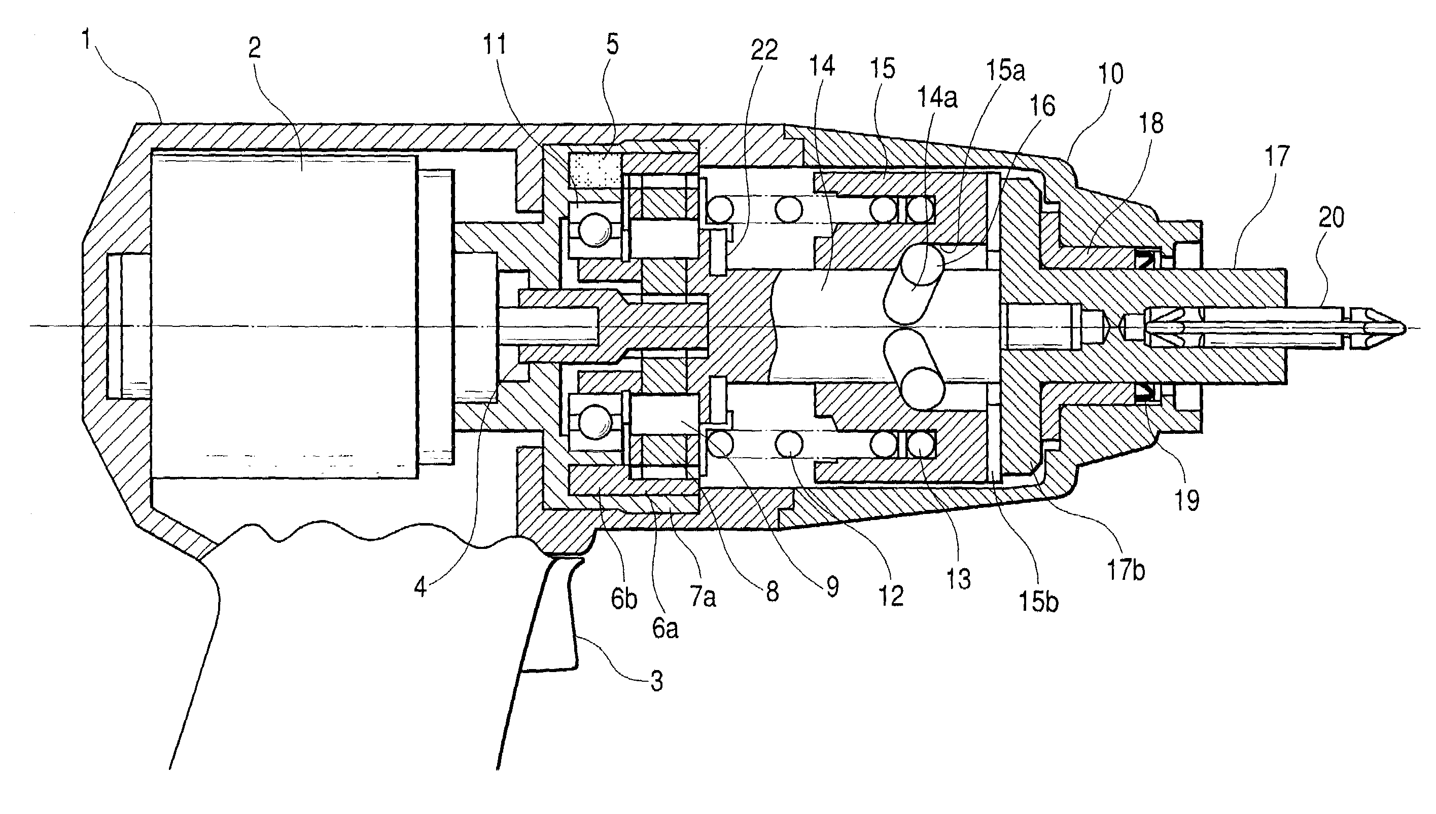
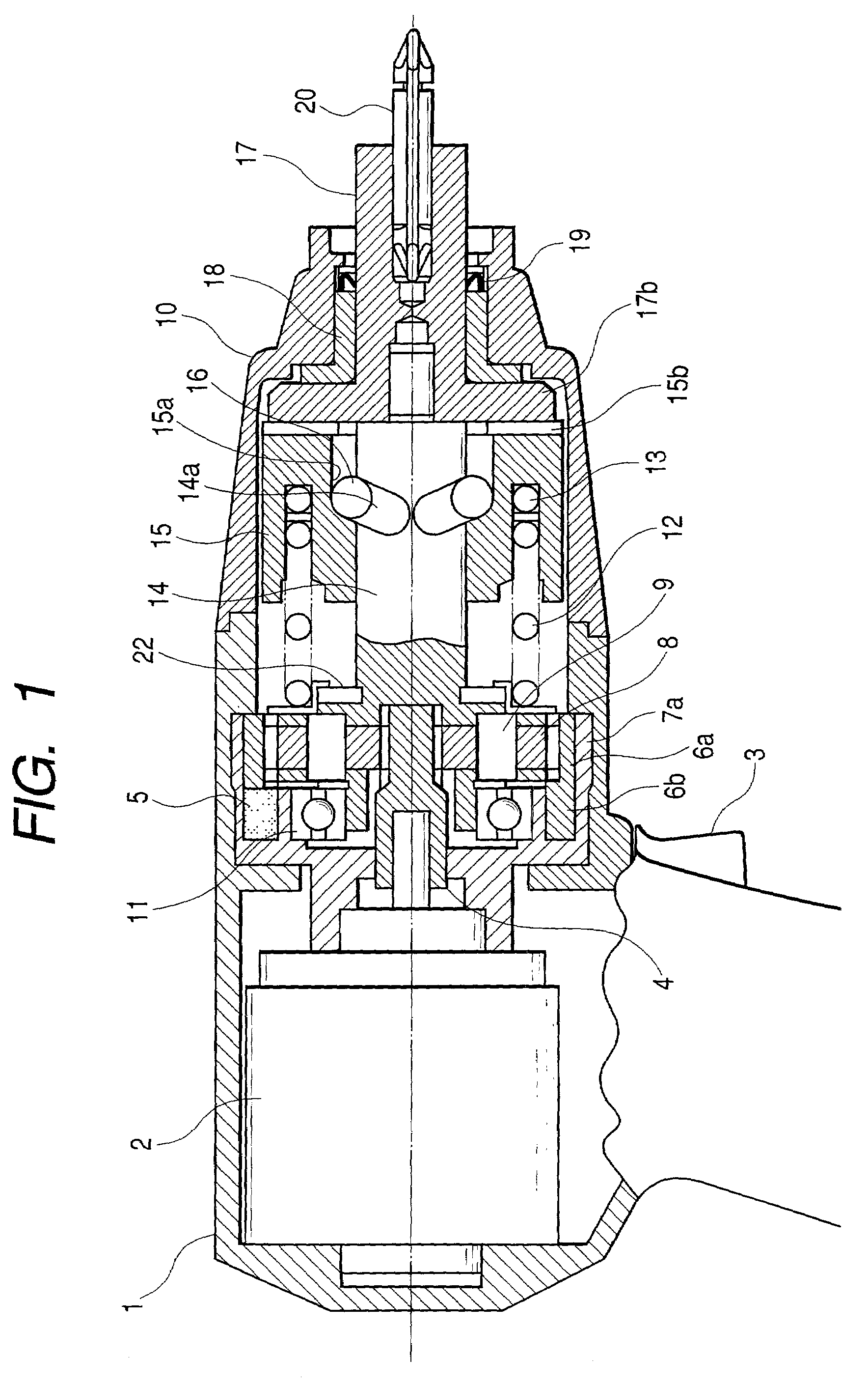
[0017]An impact tool of this embodiment will now be described with reference to FIGS. 1 to 6. FIGS. 1 and 2 show a first embodiment, and FIG. 1 is a partly-omitted, vertical cross-sectional, side-elevational view showing the impact tool, and FIG. 2 is an exploded view showing an impact damping mechanism mounted on the impact tool. In FIGS. 1 and 2, a motor 2, serving as a drive source, a speed reduction mechanism portion 8 for transmitting a rotational power of a pinion 4 which is an output shaft of the motor 2, a spindle 14 for transmitting the rotational power from the speed reduction mechanism portion 8, a hammer 15, which is rotatable and movable in a direction of the axis of rotation through steel balls 16 inserted in cam grooves 14a formed in the spindle 14, an anvil 17, having anvil claws 17b which are struck by a plurality of hammer claws 15b, provided at the hammer 15, to be rotated, an end tool 20, releasably attached to the anvil 17, and a spring 12, normally urging the h...

second embodiment

[0021]FIGS. 3 and 4 show a second embodiment, and FIG. 3 is a partly-omitted, vertical cross-sectional, side-elevational view showing an impact tool, and FIG. 4 is an exploded view showing an impact damping mechanism mounted on the impact tool. The impact damping mechanism is mounted on the impact tool shown in FIG. 3, and in this impact damping mechanism, projections 6d are formed on an outer surface of a fixed gear 6c as shown in FIG. 4, and holes 7d are formed respectively in those portions of a fixed gear support jig 7c (which is mounted within a housing 1) corresponding respectively to the projections 6d on the outer surface of the fixed gear 6c, and impact damping members 5c and 5d are inserted in these holes 7d.

[0022]In this impact damping mechanism, the fixed gear 6c is combined with the fixed gear support jig 7c in such a manner that the projection 6d of the fixed gear 6c is inserted between the impact damping members 5c and 5d. Therefore, the load is supported at a more r...

third embodiment

[0023]FIGS. 5 and 6 show a third embodiment, and FIG. 5 is a partly-omitted, vertical cross-sectional, side-elevational view showing an impact tool, and FIG. 6 is an exploded view showing an impact damping mechanism mounted on the impact tool. The impact damping mechanism is mounted on the impact tool shown in FIG. 5, and in this impact damping mechanism, a fixed gear 6 and a fixed gear support jig 7e are fixedly secured to each other as shown in FIG. 6, and impact damping members 5e and 5f are provided respectively on opposite sides of each of projections 7f which are rotation stoppers for preventing the rotation of the fixed gear support jig 7e relative to a housing 1.

[0024]In this impact damping mechanism, that side of each impact damping member 5e, 5f, facing in the same direction as the projection 7f, is held by a rib 1a of the housing 1 of the body, and besides the impact damping members 5e and 5f are provided between a bearing 11 and the housing 1, and therefore a rotational ...


PUM

PropertyMeasurementUnit
rotational impact forceaaaaaaaaaa
rotational poweraaaaaaaaaa
speedaaaaaaaaaa

Abstract

A power tool includes a powered drive source, a speed reduction mechanism portion for transmitting a rotational power of the drive source, a striking mechanism portion for converting the rotational power of the speed reduction mechanism portion into a striking force, an end tool for outputting the striking force and a rotational force through the striking mechanism portion, and an impact damping mechanism for damping the impact of the end tool in a direction of rotation of the speed reduction mechanism.

Description

BACKGROUND OF THE INVENTION[0001]1. Field of the Invention[0002]This invention relates to a power tool such as an impact screwdriver and an oil pulse screwdriver.[0003]2. Description of the Related Art[0004]A conventional power tool will be described with reference to FIG. 8. FIG. 8 is a partly-omitted, vertical cross-sectional, side-elevational view showing an impact tool for imparting a rotational force and a striking force to an end tool 20 such as a bit. Generally, a motor 2, serving as a drive source, a speed reduction mechanism portion 8 for transmitting a rotational power of a pinion 4 which is an output shaft of the motor 2, a spindle 14 for transmitting the rotational power from the speed reduction mechanism portion, a hammer 15, which is rotatable and movable in a direction of the axis of rotation through steel balls 16 inserted in cam grooves 14a formed in the spindle 14, an anvil 17, having anvil claws 17b which are struck by a plurality of hammer claws 15b, provided at ...

Claims


Application Information

Patent Timeline
Patent Type & Authority Patents(United States)
IPC IPC(8): B25B19/00B25B21/02
CPCB25B21/02Y10T74/19907Y10T74/19898Y10T74/19633
Inventor SAITO, TAKUMAOHTSU, SHINKIOHMORI, YASUKIYOSHIMIZU, CHIKAIOOMORI, KATSUHIROWATANABE, MASANORI
Owner KOKI HLDG CO LTD
Why Eureka
Try Eureka