Method and devices for decreasing elevated pulmonary venous pressure

a technology of pulmonary veins and venous pressure, which is applied in the field of methods and devices for decreasing elevated pulmonary veins, can solve the problems of pulmonary edema, impaired pulmonary vein partitioning, and pathologic dilatation of veins in the lower extremities, and achieves high low and the effect of reducing the mean pulmonary venous pressur

Inactive Publication Date: 2006-05-23
SHAKNOVICH ALEXANDER
View PDF14 Cites 65 Cited by
  • Summary
  • Abstract
  • Description
  • Claims
  • Application Information

AI Technical Summary

Benefits of technology

[0011]The prosthetic valves of the invention, in their properly implanted condition, configuration and orientation, are capable of permitting ingress of blood from the pulmonary vein(s) into the left atrium during that portion of the cardiac cycle when the pressure in the pulmonary vein(s) slightly exceeds the pressure in the left atrium, and are capable of preventing egress of blood from the left atrium into the pulmonary vein(s) during that portion of the cardiac cycle when the pressure in the left atrium slightly exceeds the pressure in the pulmonary vein(s).

Problems solved by technology

When these venous valves in the lower extremities are incompetent, venous blood pressure in the foot becomes predominantly equal to the sum of the relatively low pressure in the right atrium and relatively high hydrostatic pressure of the column of venous blood between the right atrium and the foot, often resulting in pathologic dilatation of the veins in the lower extremities and / or edema.
When mitral valve function is compromised, partitioning of the left ventricle during systole from the left atrium, and therefore from the pulmonary veins, becomes impaired.
As a result, relatively high left ventricular systolic pressure is transmitted, with a phase shift, into the pulmonary veins, often producing marked elevation of the mean pulmonary venous pressure, which can lead to pulmonary edema and congestive heart failure (“CHF”).
CHF is a major cause of cardiovascular morbidity and mortality, affecting tens of millions of patients worldwide.
In a substantial number of patients, surgical valve replacement is not possible, or is associated with an unacceptably high risk of morbidity and / or mortality.
In other patients, the mitral valve becomes narrowed or stenotic and fails to open properly during diastole.

Method used


Image

  • Method and devices for decreasing elevated pulmonary venous pressure
  • Method and devices for decreasing elevated pulmonary venous pressure
  • Method and devices for decreasing elevated pulmonary venous pressure

Examples


Embodiment Construction

5.1 Prosthetic Pulmonary Valves

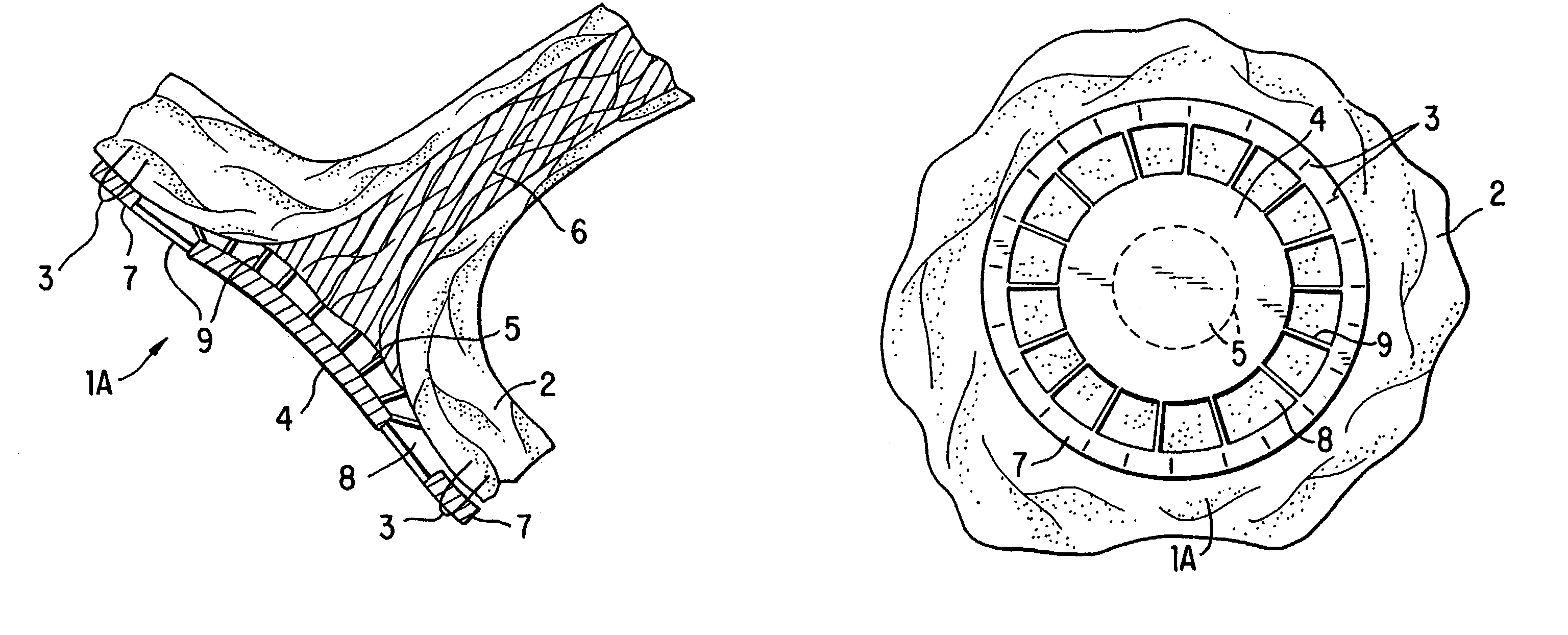
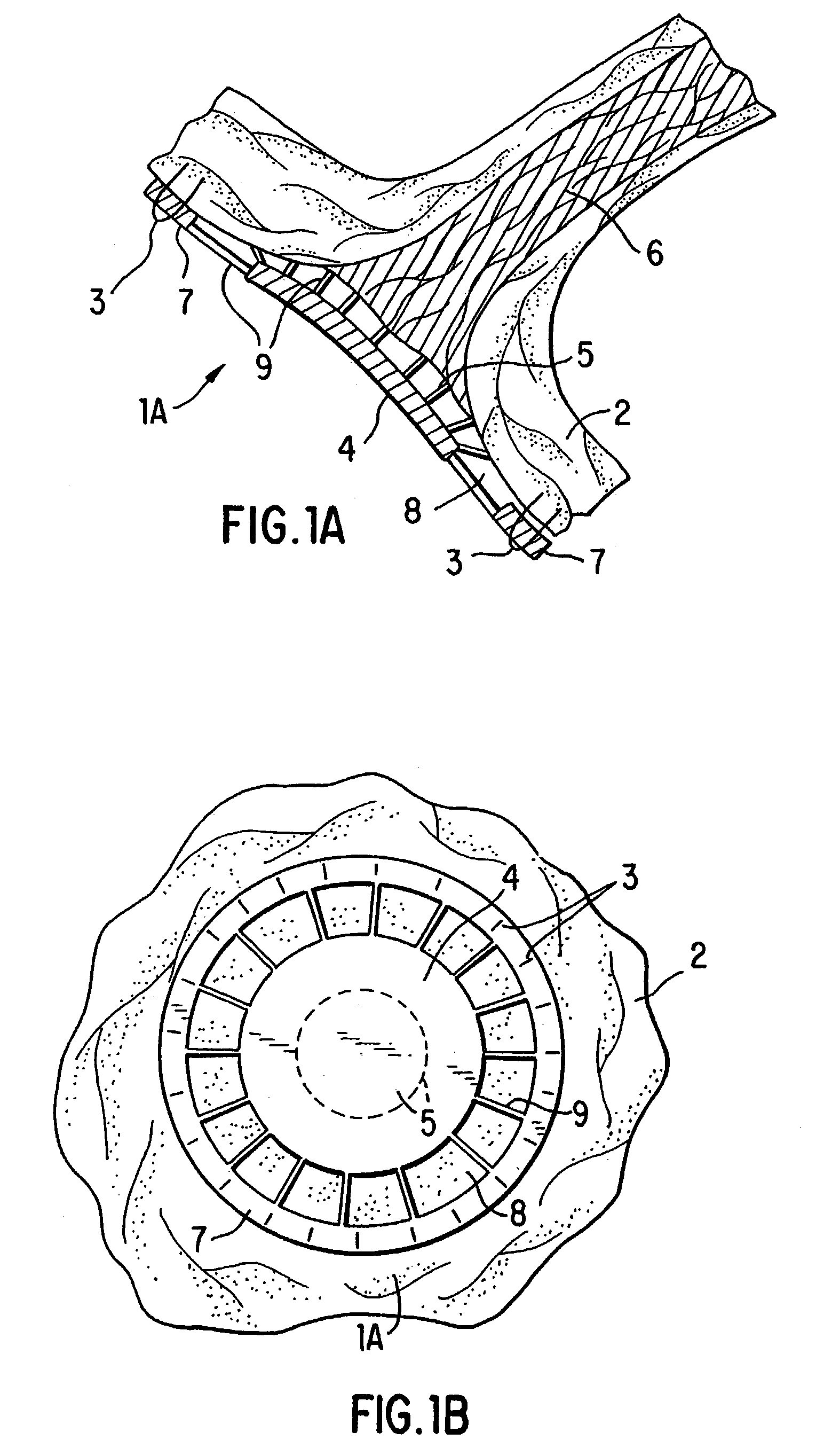
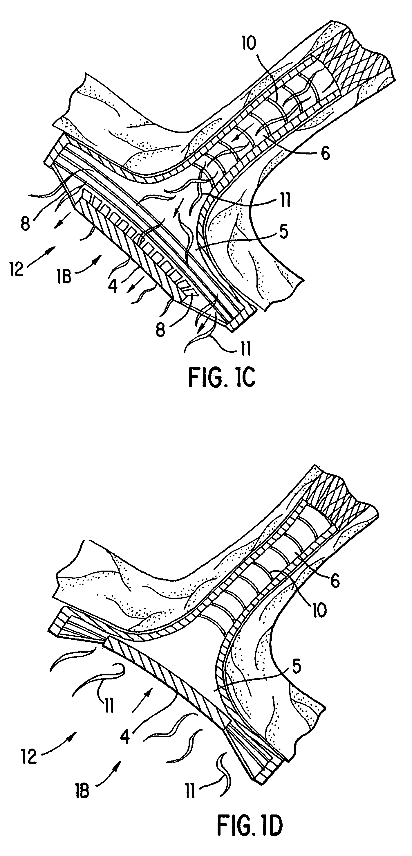
[0021]The present invention provides for prosthetic pulmonary valves, systems and methods for their delivery, and methods of using such valves for treating subjects exhibiting or at risk for developing elevated pulmonary venous pressures.

[0022]The term “prosthetic”, as used herein, refers to the fact that the valves of the invention are implanted into subjects, and does not suggest that the valves replace any naturally occurring valve, as pulmonary vein valves are not known to occur in mammals.

[0023]An expandable pulmonary vein prosthetic valve for percutaneous delivery, placement and implantation or for implantation during surgical procedures desirably exhibits a smaller relative circumference and area in its unexpanded configuration to facilitate delivery and placement. That portion of a valve which is retained within the pulmonary vein preferably conforms to the dimensions of the vein, particularly the diameter of the vein in transverse section. Loc...


PUM


Abstract

The present invention relates to the implantation of one or more prosthetic valve(s) in the pulmonary vein(s) of a subject as a means of decreasing or preventing an increase in pulmonary venous pressure. The present invention accordingly provides for novel treatment strategies for the treatment of medical disorders associated with elevated pulmonary venous pressure, including congestive heart failure, as well as for prosthetic pulmonary vein valves and their delivery systems. Expandable as well as fixed-dimension non-expandable pulmonary vein prosthetic valves for implantation by a variety of surgical and percutaneous procedures are also described.

Description

[0001]This application is a divisional of U.S. application Ser. No. 09 / 813,182, filed Mar. 20, 2001, now U.S. Pat. No. 6,572,652, which claims priority to U.S. Provisional Application No. 60 / 228,574, filed Aug. 29, 2000.1. INTRODUCTION[0002]The present invention relates to the implantation of one or more prosthetic valve(s) in the pulmonary vein(s) of a subject as a means of decreasing or preventing an increase in pulmonary venous pressure. The present invention accordingly provides novel strategies for the treatment of medical disorders associated with elevated pulmonary venous pressure, including congestive heart failure, as well as for prosthetic pulmonary vein valves and their delivery systems. Expandable as well as fixed-dimension non-expandable pulmonary vein prosthetic valves for implantation by a variety of surgical and percutaneous procedures are also described.2. BACKGROUND OF THE INVENTION2.1. Physiologic Venous Valves[0003]Certain larger veins in the lower extremities of...

Claims


Application Information

Patent Timeline
Patent Type & Authority Patents(United States)
IPC IPC(8): A61F2/24A61F2/82
CPCA61F2/24A61F2/2433A61F2/2475A61F2/2436Y10S623/904A61F2002/821A61F2/2412
Inventor SHAKNOVICH, ALEXANDER
Owner SHAKNOVICH ALEXANDER
Why Eureka
Try Eureka