Power-on detect circuit for use with multiple voltage domains

a detection circuit and voltage domain technology, applied in the field of integrated circuits, can solve the problem that the output of the level shifter may not be defined, and achieve the effect of reducing the propagation of an x

Inactive Publication Date: 2006-05-23
INTEL CORP
View PDF6 Cites 31 Cited by
  • Summary
  • Abstract
  • Description
  • Claims
  • Application Information

AI Technical Summary

Benefits of technology

[0030]In particular, POD 100 is used to qualify any signal transitioning between the two voltage domains. For the embodiment, level shift arrangement 306 includes level shifter 208 and AND gate 212 coupled to each other and the other elements as shown. In this embodiment, a logic signal, in2204, may be input from the V2 voltage domain. In2204 may enter a level shifter 208 to be shifted from the V2 voltage domain into the V1 voltage domain. The output may be gated after the level shifter 208 by a control signal indicating that the V2 voltage has reached the desired nominal level, e.g. V1V2good, using AND gate 212. When the AND gate 212 receives the control signal it may provide a level shifted logic signal, out1210, to operational circuit 304 of the V1 voltage domain. The arrangement may help to reduce the propagation of an X (unknown signal) by the level shifter 208 for the case where the destination voltage supply (e.g., V1) is valid but the driving supply (e.g., V2) is not. In various embodiments, integrated circuit 300 is a general purpose microprocessor, operational circuit 304 may be the core logic of the microprocessor, while operational circuit 302 may be the I / O section of the microprocessor.

Problems solved by technology

Unfortunately, the level shifter output may be an undefined signal if the voltage in the second voltage domain has not reached the nominal voltage level.

Method used


Image

  • Power-on detect circuit for use with multiple voltage domains
  • Power-on detect circuit for use with multiple voltage domains
  • Power-on detect circuit for use with multiple voltage domains

Examples


Embodiment Construction

[0011]In the following detailed description, reference is made to the accompanying drawings that form a part hereof, wherein like numerals designate like parts throughout, and in which is shown by way of illustration of specific embodiments in which the invention may be practiced. It is to be understood that other embodiments may be utilized and structural or logical changes may be made without departing from the scope of the embodiments of the present invention. Therefore, the following detailed description is not to be taken in a limiting sense and the scope of the embodiments of the present invention is defined by the appended claims and their equivalents.

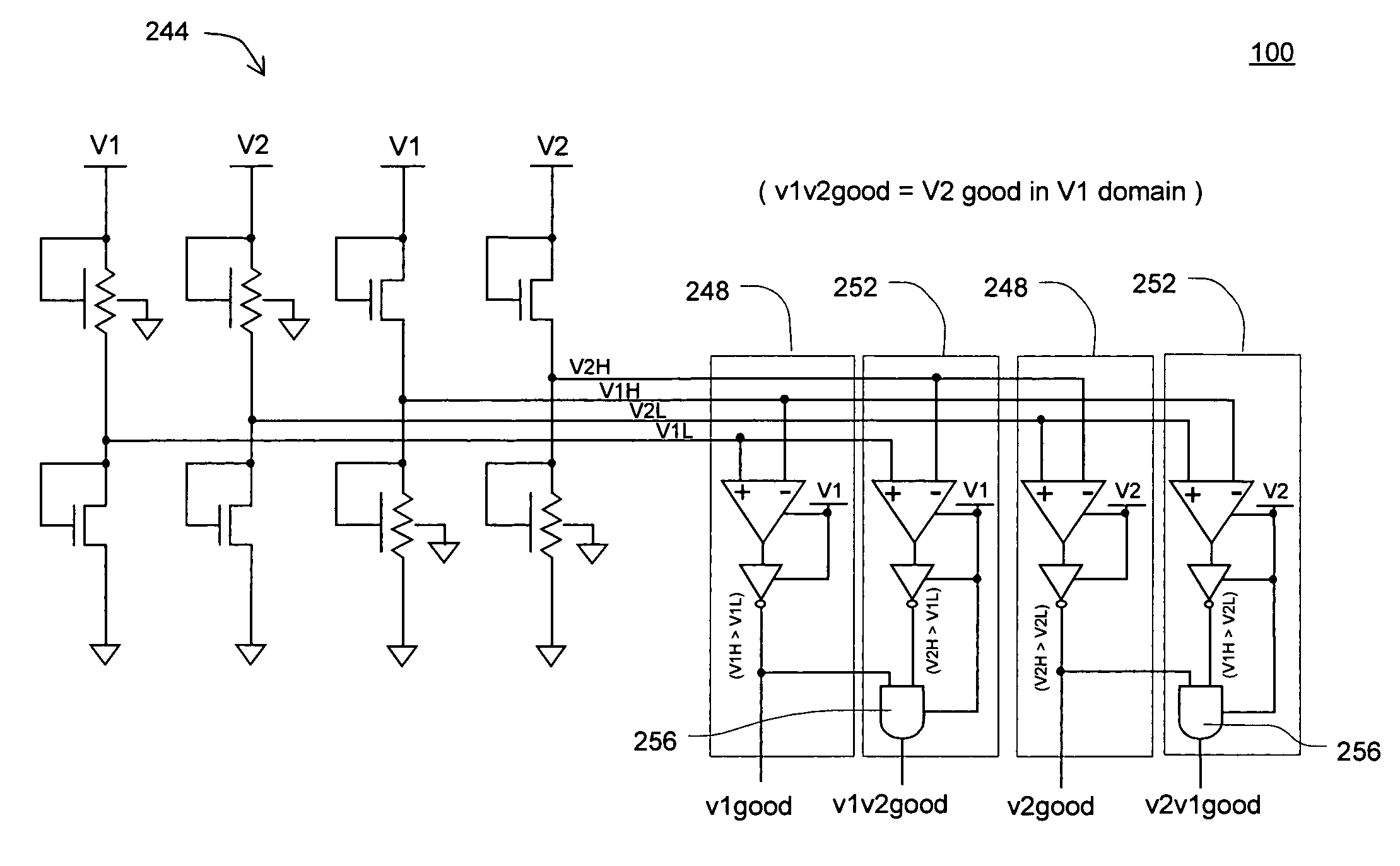
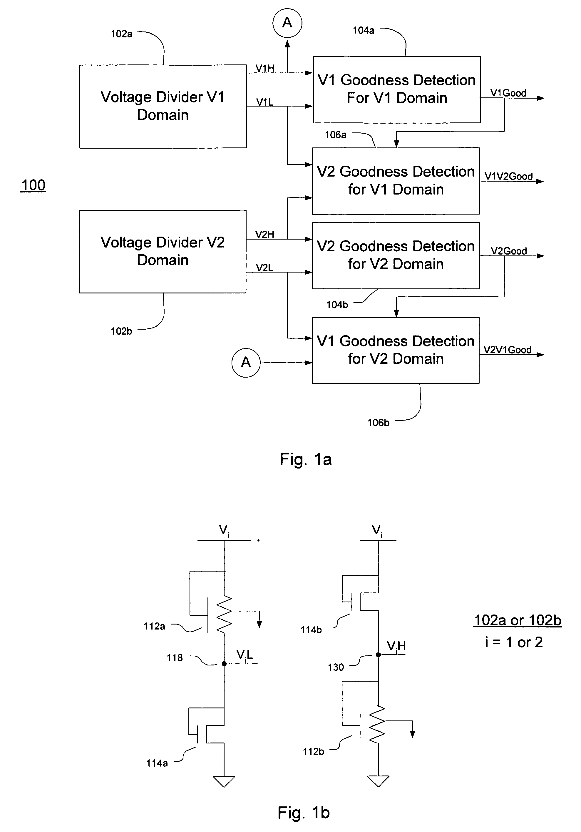
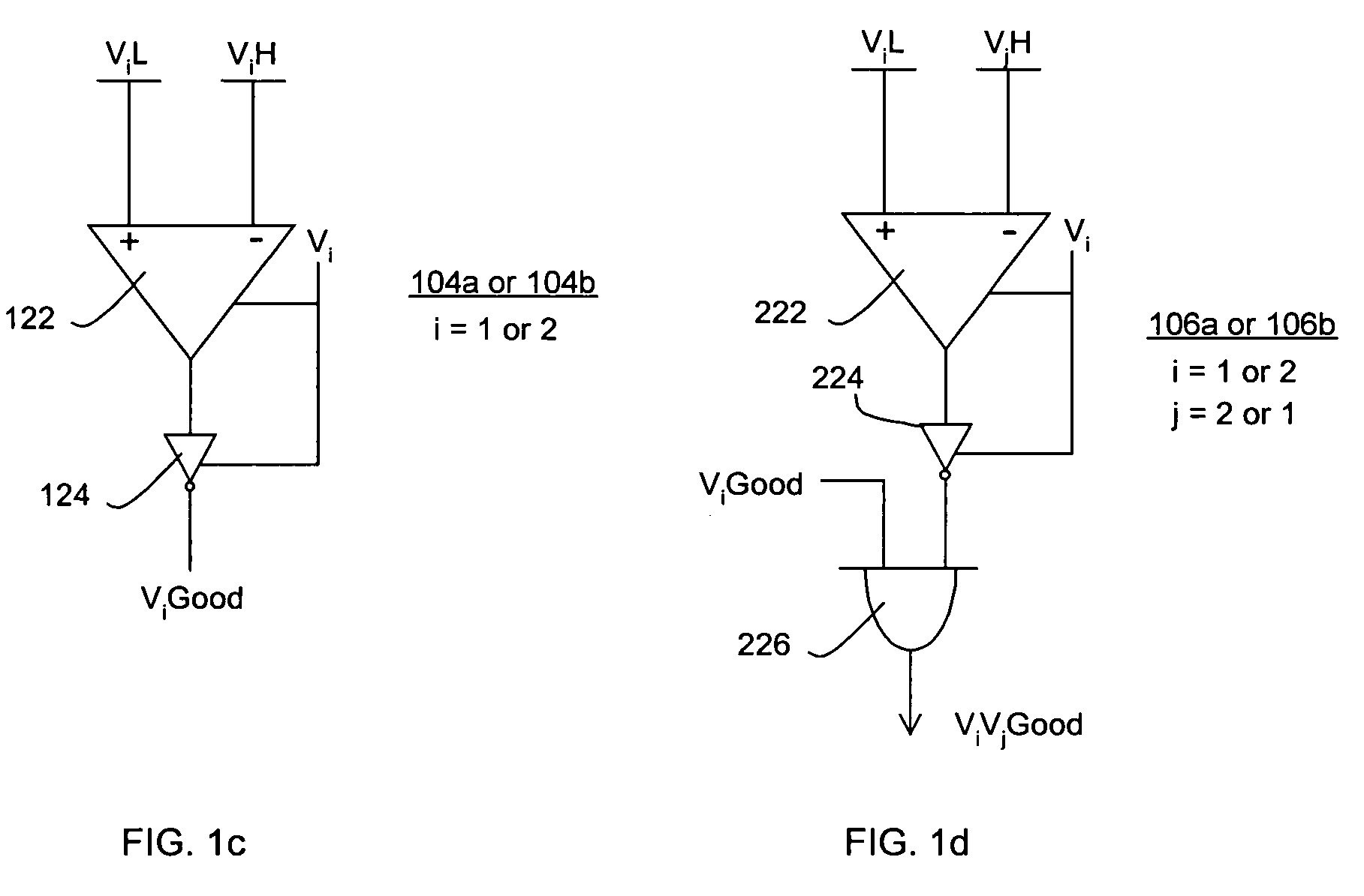
[0012]FIGS. 1a–1d illustrate a power-on detect (POD) circuit 100 that may be used to assure voltage levels of multiple voltages for multiple voltage domains, in accordance with one embodiment of this invention. In particular, for this embodiment, POD circuit 100 may be used to assure the voltage levels of first (V1) and second (...


PUM


Abstract

Embodiments of the present invention include a circuit, a method, and a system for power-on detect circuitry for use with multiple voltage domains.

Description

FIELD OF THE INVENTION[0001]Disclosed embodiments of the present invention relate to the field of integrated circuits (IC), and more particularly to providing signal integrity across multiple voltage domains of the IC.BACKGROUND OF THE INVENTION[0002]Many types of modern electronic devices may incorporate multiple voltage domains. For example, a modern microprocessor chip may include core logic that operates in one voltage domain while interacting with input / output (I / O) circuitry operating in another.[0003]During the initial power up sequencing the different voltage domains may reach a nominal power level at different times. If logic in a first voltage domain is required to function only when the voltages of both domains are at their nominal levels, the logic in the first voltage domain may need an indication that the signal(s) outputted by the second domain logic is(are) valid. Prior art methods have attempted to accomplish this by sending a signal through a level shifter from the...

Claims


Application Information

Patent Timeline
Patent Type & Authority Patents(United States)
IPC IPC(8): H03L7/00
CPCH03K17/223
Inventor PARKER, RACHAEL J.NEIDENGARD, MARK L.OTT, PATRICK J.TAYLOR, GREGORY F.
Owner INTEL CORP
Why Eureka
Try Eureka