Method for filtering digital images, and a filtering device

a digital image and filtering technology, applied in the field of digital image filtering and filtering devices, can solve the problems of significant technical problems relating to spatial and temporal propagation, inability to use motion compensation prediction when coding, and visible edges in the image reproduced by the receiver

Inactive Publication Date: 2008-06-17
NORDIC INTERACTIVE TECH LLC
View PDF16 Cites 22 Cited by
  • Summary
  • Abstract
  • Description
  • Claims
  • Application Information

AI Technical Summary

Benefits of technology

[0030]According to a first aspect of the invention, there is provided a method for reducing blocking and other visual artefacts (which are mainly caused by blocking artefacts) from a frame that has been coded by blocks, characterized in that the filtering is performed after the current block is decoded and there is a boundary available for filtering between the current block and a previously decoded block.
[0043]The method and associated device according to the invention significantly limits propagation of visual anomalies due to blocking artefacts from previously reconstructed blocks to subsequently reconstructed blocks within the same frame, or within the same segment, if independent segment decoding is used. Propagation of blocking artefacts from one frame to the next is also reduced. By using the method and device according to the invention a larger number of blocking and blocking-related artefacts can be removed without weakening the real edges within the image unreasonably.

Problems solved by technology

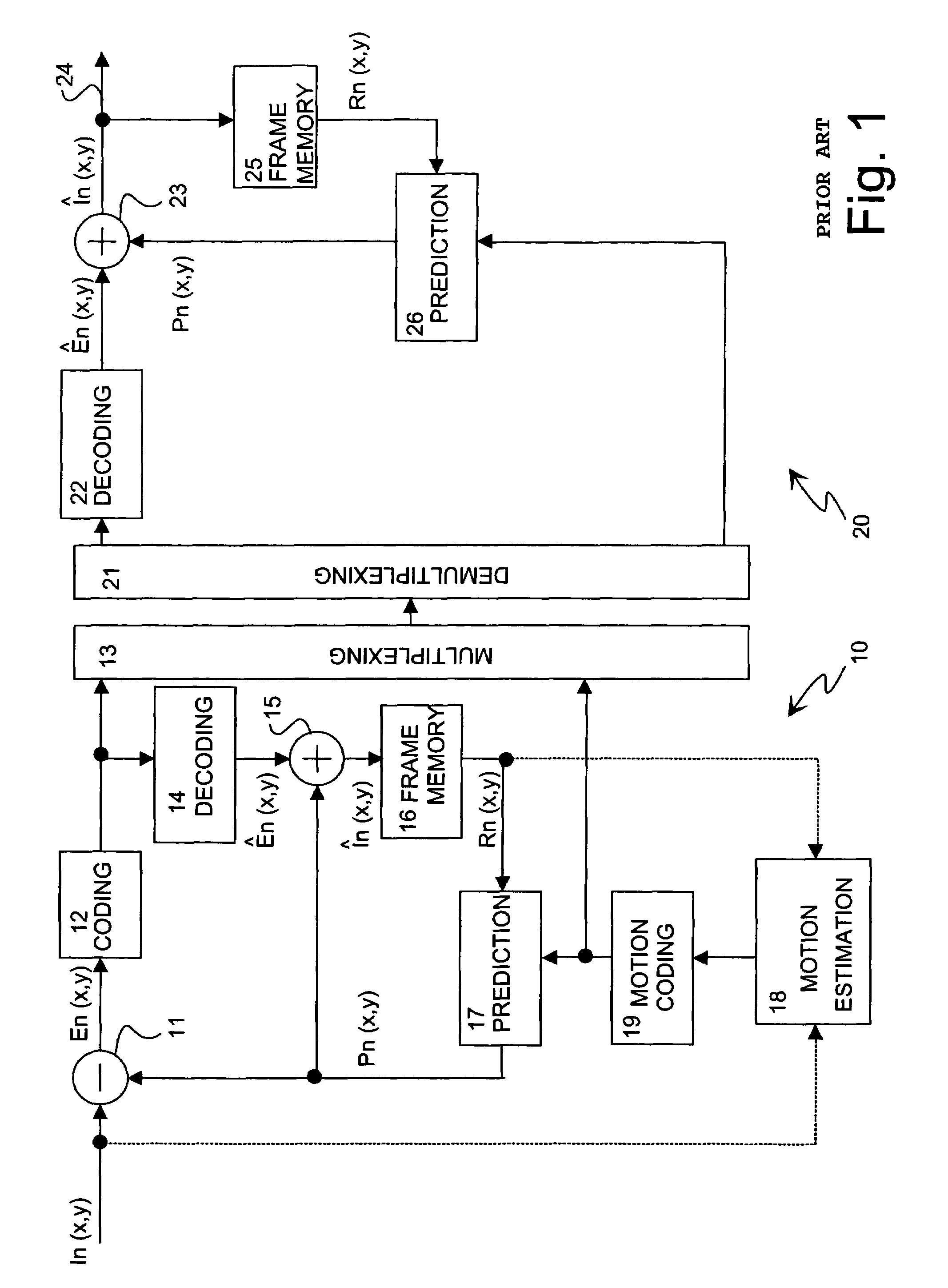
Some frames can be partly, or entirely, so difficult to predict using only the reference frame Rn(x,y) that it is not practical to use motion compensated prediction when coding them.
Quantization causes rounding errors, which can become visible in an image reconstructed from blocks, so that there is a discontinuity of pixel values at the boundary between adjacent blocks.
Because a certain decoded frame is used to calculate the prediction frame for subsequent predicted (P) frames, these errors can be propagated in sequential frames, thus causing visible edges in the image reproduced by the receiver.
Image errors of this type are called blocking artefacts, Furthermore, if intra-prediction is used, blocking artefacts may also propagate from block to block within a given frame.
It should therefore be appreciated that there exists a significant technical problem relating to the spatial and temporal propagation of blocking artefacts in digital images that are coded for transmission and subsequently decoded.
It has been found that prior art methods also tend to remove lines that belong to real features of the image.
On the other hand, prior art methods are not always capable of removing all blocking or blocking-related artefacts.

Method used


Image

  • Method for filtering digital images, and a filtering device
  • Method for filtering digital images, and a filtering device
  • Method for filtering digital images, and a filtering device

Examples


Embodiment Construction

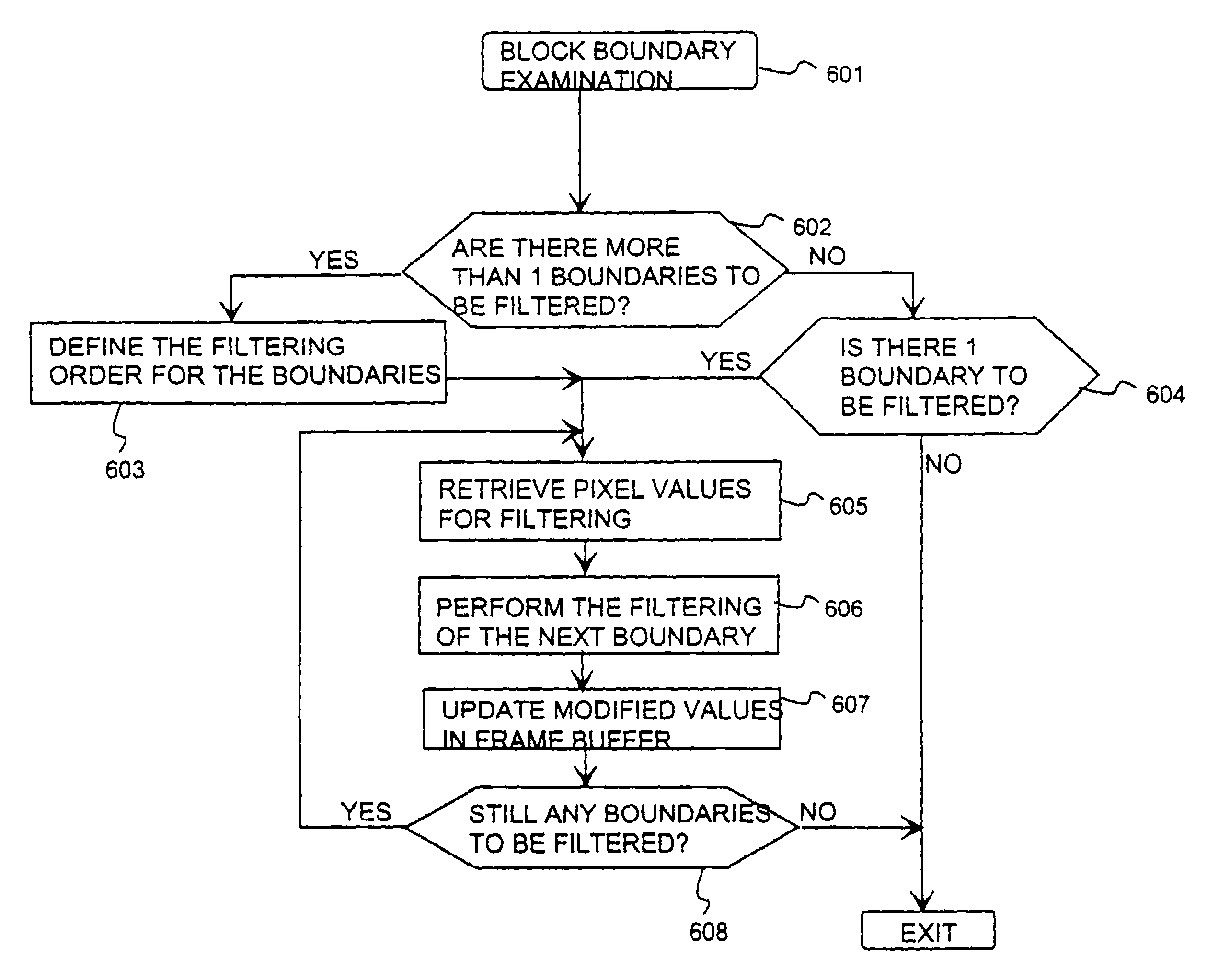
[0052]In the following description of the invention and its preferred embodiments, reference will be made mostly to FIGS. 2 to 6.

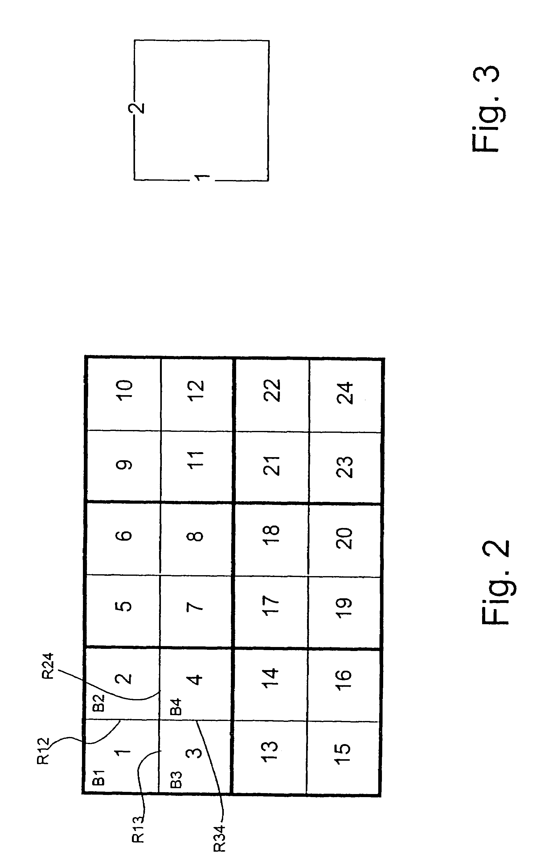
[0053]In the following, the operation of a digital image decoder is described. In a digital image transfer system according to the invention, such as that illustrated in FIG. 5, the block and block boundary scanning order used in the encoder and decoder are the same, i.e. known to both encoder and decoder. However, the particular scanning order chosen is not essential for implementation of the method according to the invention. FIG. 2 shows an advantageous scanning order for a frame comprising groups of blocks, e.g. macroblocks. First, the top-left block B1 is decoded, i.e. pixel values representing e.g. the luminance information of the block are reconstructed and saved into a frame buffer. Then, the top-right block B2 is decoded and saved into the frame buffer. Now, the first vertical boundary R12 between the top-left block B1 and top-right block B2 has a...


PUM


Abstract

The invention relates to a method for reducing visual artefacts in a digital image, which is coded by blocks (B1, B2, B3, B4) and then decoded. In the method filtering is performed to reduce visual artefacts due to a boundary (R12, R13, R24, R34) between a current block and an adjacent block (B1, B2, B3, B4). The filtering is performed after the current block (B1, B2, B3, B4) is decoded and there is a boundary available for filtering between the current block and a previously decoded block.

Description

CROSS-REFERENCE TO RELATED APPLICATIONS[0001]Not applicableSTATEMENT REGARDING FEDERALLY SPONSORED RESEARCH OR DEVELOPMENT[0002]Not applicableINCORPORATION-BY-REFERENCE OF MATERAL SUBMITTED ON A COMPACT DISC[0003]Not applicableBACKGROUND OF THE INVENTION[0004]1. Field of the Invention[0005]The present invention relates to a method for reducing visual artefacts in a digital image, which is encoded and decoded by blocks, in which filtering is performed to reduce visual artefacts due to a boundary between a current block and an adjacent block. The present invention also relates to a device for reducing visual artefacts in a digital image, which is encoded and decoded by blocks, the device comprising means for performing filtering to reduce visual artefacts due to a boundary between a current block and an adjacent block. The present invention also relates to an encoder comprising means for coding and means for locally decoding a digital image by blocks, which encoder comprises means for...

Claims


Application Information

Patent Timeline
Patent Type & Authority Patents(United States)
IPC IPC(8): G06K9/40G06K9/46H04N7/12H04J3/00H04N1/409H04N1/41H04N19/80H04N19/86H04N19/89H04N19/895
CPCH04N19/527H04N19/895H04N19/86H04N19/80
Inventor LAINEMA, JANIDOBRIN, BOGDAN-PAULKARCZEWICZ, MARTA
Owner NORDIC INTERACTIVE TECH LLC
Why Eureka
Try Eureka