
Housing

Inactive Publication Date: 2015-03-26
JAGUAR LAND ROVER LTD
View PDF5 Cites 11 Cited by
  • Summary
  • Abstract
  • Description
  • Claims
  • Application Information

AI Technical Summary

Benefits of technology

The present invention relates to a transmission housing with improved vibration control. The housing includes at least one vibration control panel or at least one elongate undulation in the sidewall. These features can help to reduce noise and vibration output, and can improve the overall performance of the transmission housing. The vibration control panels can be positioned and sized to tune the system and can be integrated with the sidewall. The elongate undulations can provide stiffness and reinforcement without adding much weight or thickness to the housing. Overall, these features can make the transmission housing more efficient and effective in transmitting power.

Problems solved by technology

In use, the transmission 1 is subject to vibrations and combustion noise from the engine, motor noise from an electric motor or contact noise from the transmission gears.
However, the efficacy of the sound-dampening jacket may vary for different operating conditions of the engine and will invariably increase the weight and cost of the transmission 1, and affect serviceability of the unit.
The jackets sound dampening performance can be adversely affected if holes or gaps are present, and its durability can be adversely affected if the local environment is subject to radiated heat from the powertrain or its associated components (exhaust, EGR etc).

Method used


Image

  • Housing
  • Housing
  • Housing

Examples


first embodiment

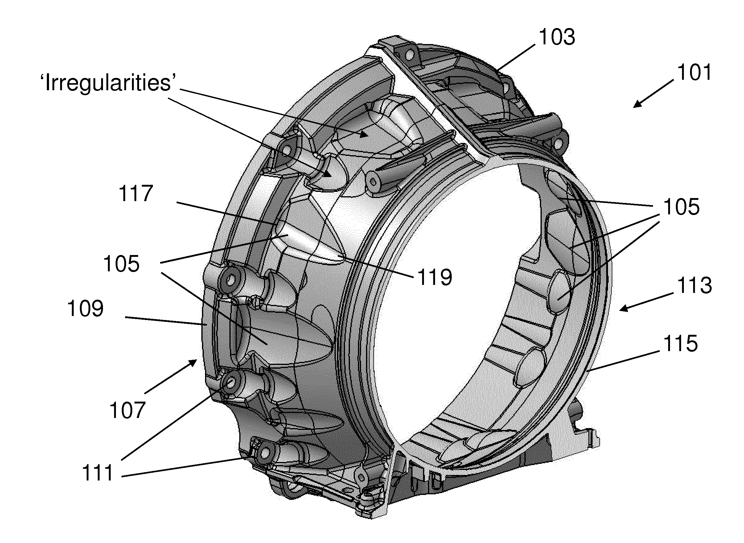
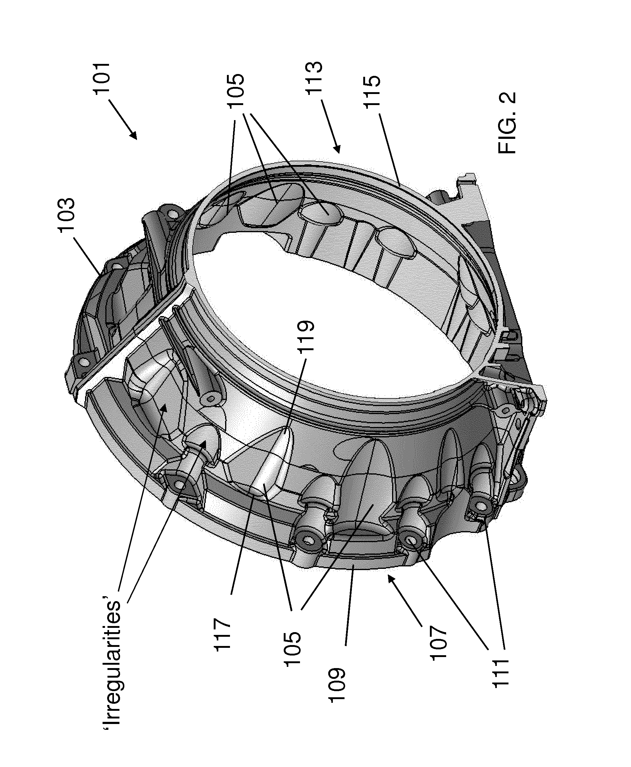
[0053]A contoured bellhousing 101 in accordance with the present invention is shown in FIGS. 2, 3 and 4. The contoured bellhousing 101 comprises a housing 103 having a plurality of vibration control panels 105 which, as described herein, are adapted to control the propagation of vibrations. The contoured bellhousing 101 in the present embodiment forms part of a north / south layout transmission housing for use in an automotive vehicle having an internal combustion engine (not shown).

[0054]The housing 103 is a single-piece casting having a generally truncated conical form for accommodating a flywheel and clutch mechanism. A first end 107 of the housing 103 comprises a first circular flange 109 having a series of circumferentially spaced apertures 111 for mounting the contoured bellhousing 101 to a casing of the internal combustion engine. A second end 113 of the contoured bellhousing 101 comprises a second circular profile 115 for interfacing with, or sealing with the transmission cyli...

second embodiment

[0063]A contoured bellhousing 201 according to the present invention is shown in FIG. 6. The contoured bellhousing 201 is again for use in a north / south layout transmission for an automotive vehicle. The contoured bellhousing 201 comprises a housing 203 having an annular undulation 205 for controlling the propagation of vibrations in the contoured bellhousing 201.

[0064]The arrangement of the contoured bellhousing 201 is the same as that of the first embodiment. Specifically, the housing 203 is a single-piece casting having a generally truncated conical form. A first end 207 of the housing 203 comprises a first circular flange 209 having a series of circumferentially spaced apertures 211 for mounting the contoured bellhousing 201 to an internal combustion engine. A second end 213 of the contoured bellhousing 201 comprises a second circular profile 215 for interfacing with, or sealingly engaging a transmission cylinder 217.

[0065]As shown in FIG. 7, the annular undulation 205 forms a c...


PUM


Abstract

The present invention relates to a housing, such as a transmission housing (103; 203), configured to control vibrations. A transmission housing (103) according to a first embodiment of the present invention has one or more vibration control panels (105) formed in a sidewall of the housing (103). The vibration control panel (105) is inset from a surrounding section of the sidewall (103). A transmission housing (203) according to a second embodiment of the present invention includes an elongate undulation (205) which forms a ridge and a corresponding groove in the transmission housing (203).

Description

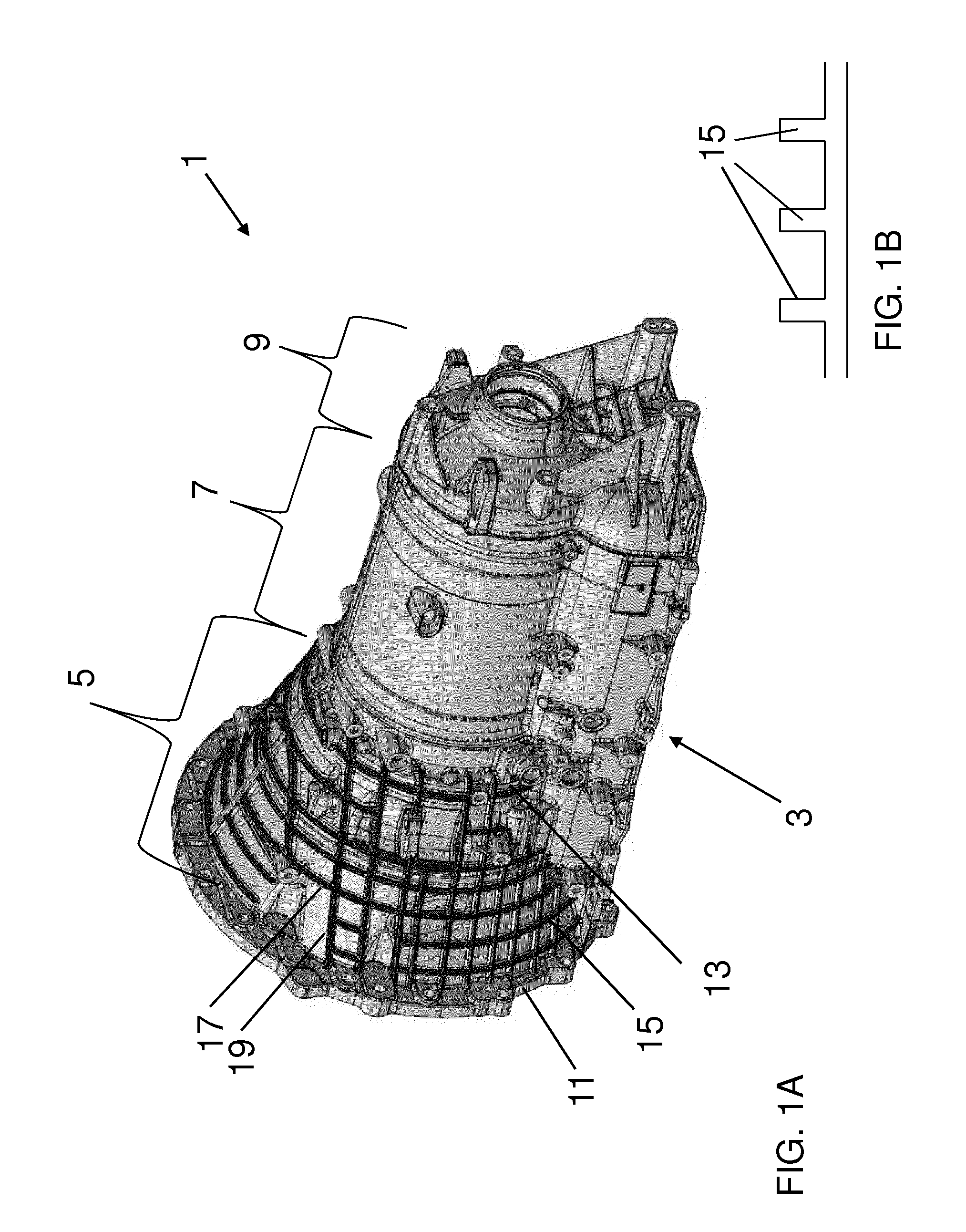
TECHNICAL FIELD[0001]The present invention relates to a housing, such as a transmission housing. The present invention has particular application in an automotive vehicle, but is not limited in this respect. Alternative automotive uses could be (but not limited to) axle covers, sump pans and engine blocks.BACKGROUND OF THE INVENTION[0002]A transmission 1 can be used to transmit power to a live axle in an automotive vehicle having an internal combustion engine. The layout of the transmission 1 could be for a manual with conventional clutch and flywheel, automated manual, automatic with torque converter, automatic with wet clutch, CVT and hybrids, in a north / south (rear wheel drive or front wheel drive), east / west (transverse and also incorporating a final drive unit) and transaxle layouts. FIG. 1A shows a north / south transmission 1 comprises a housing 3 made up of a bellhousing 5, a transmission cylinder 7 and an end section 9. The bellhousing 5 houses a power transfer mechanism (i.e...

Claims


Application Information

Patent Timeline
IPC IPC(8): F16H57/028
CPCF16H57/028F16H2057/02043F16H2057/02047Y10T74/2186
Inventor TARVER, GRAHAMCOPPING, STEVENEVIN, PATRICKCLAYTON, DAVID
Owner JAGUAR LAND ROVER LTD
Learn More