[0007] According to an exemplary embodiment of the present invention a structural element for aircraft is provided, which structural element comprises an active element and a passive element, wherein the active element is adapted for controllable or regulable active introduction of forces into the passive element, and wherein the structural element is adapted to stiffen a fuselage, to reduce deformation of the fuselage, or to dampen vibrations in the fuselage.
[0008] By designing the active element for the controllable or regulable active introduction of forces into the passive element, counterforces can be applied in a targeted way to the passive element, which counterforces for example counteract any bending of the fuselage, which bending is supported, reinforced or stabilised by the structural element. In this way the behaviour of fuselage structures may be actively influenced in order to counteract any deformation introduced by external loads. According to the invention such
active control may take place without the mentioned weight disadvantages of conventional structural stiffening involving
mass, which structural stiffening would principally entail an increased use of materials. By providing high-performance fast regulating
electronics, vibrations in the fuselage may be dampened, which in particular results in significant
noise suppression in the cabin.
[0010] Therefore, by the active introduction, in a targeted way, of forces into the passive element, structural elements may be stabilised or stiffened. In this way passenger comfort may be improved.
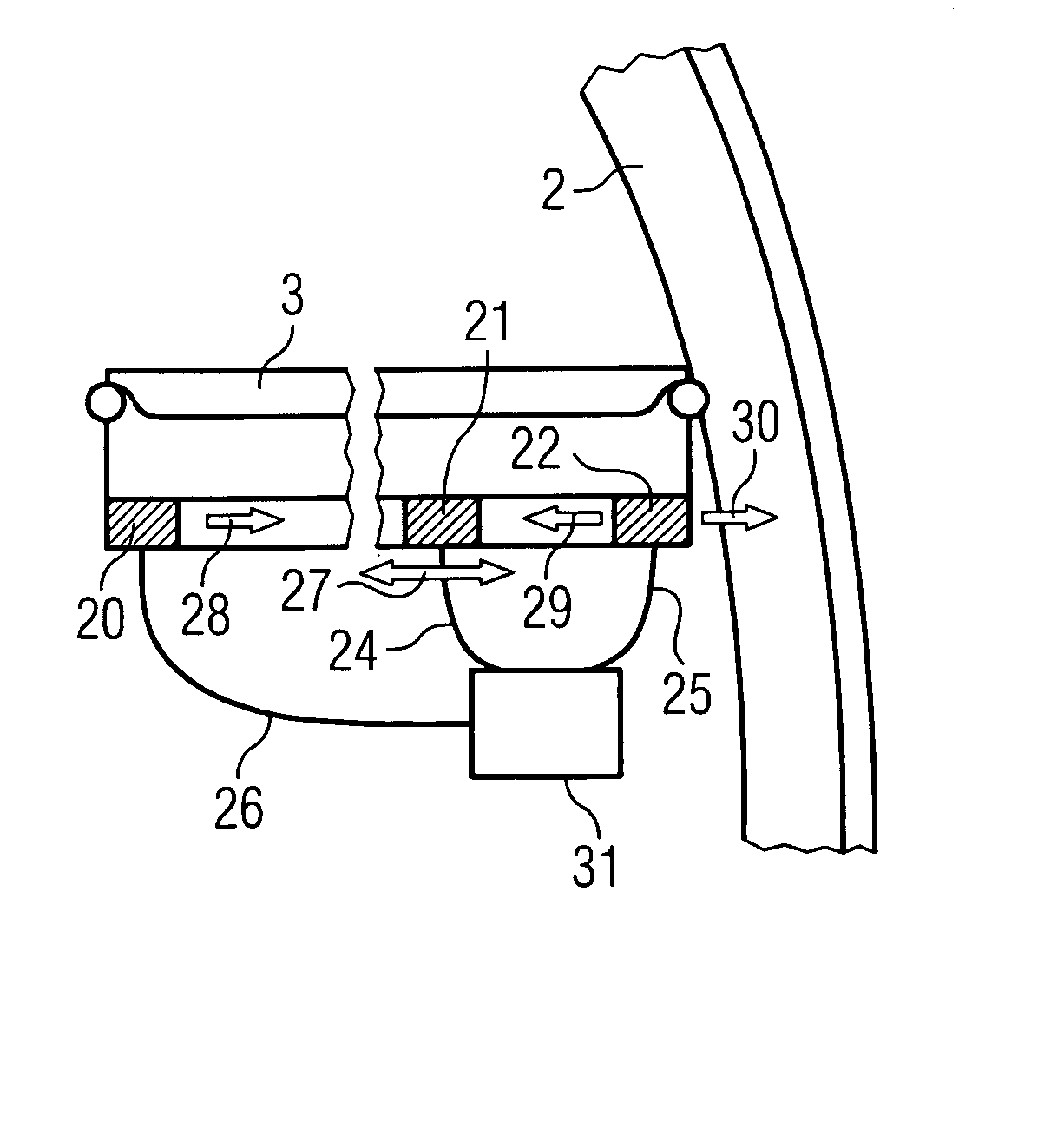
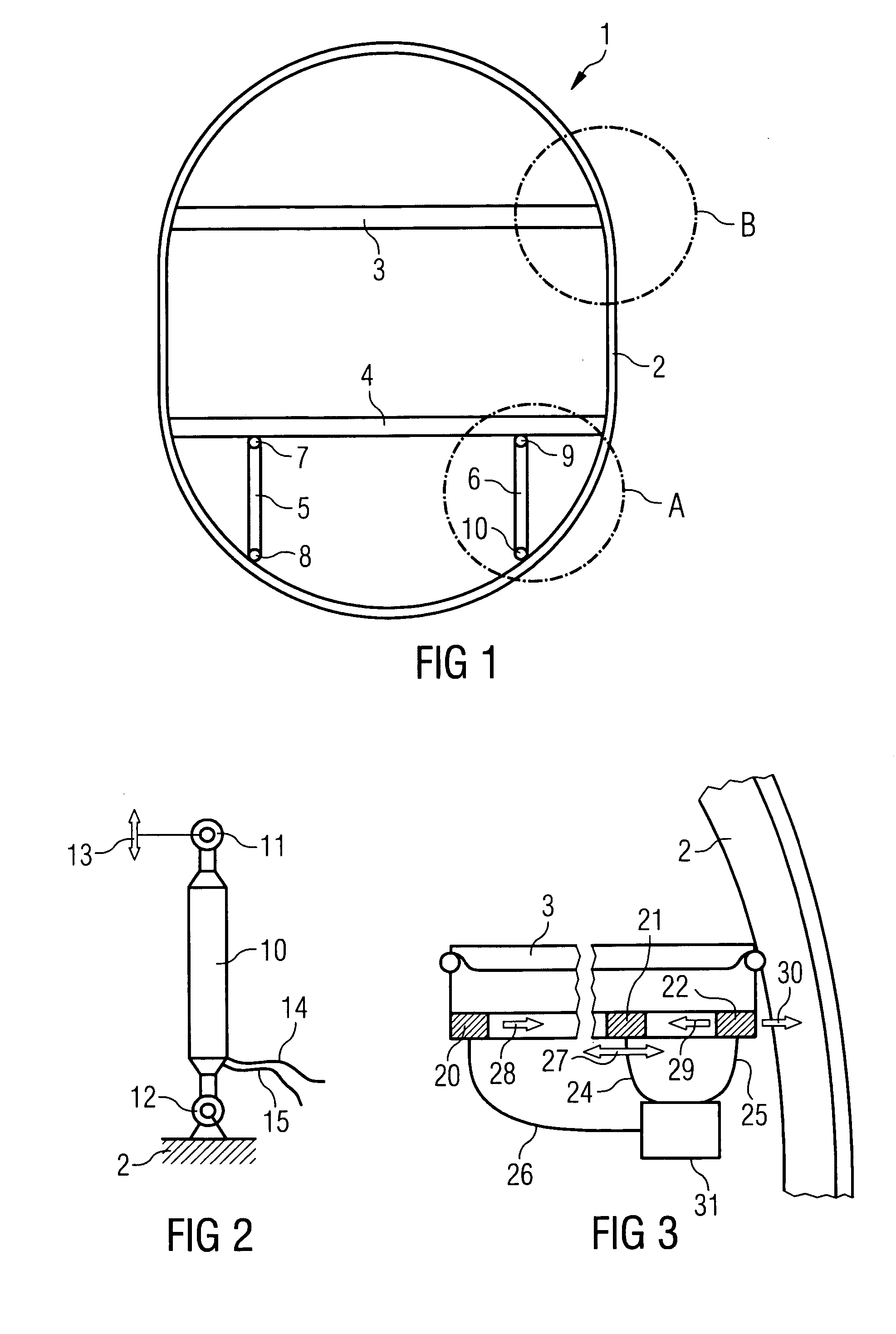
[0017] It may thus be possible to use active and so-called “smart” materials, e.g. based on piezoceramics, on
coupling positions between the floor structure and the frame, in particular the frame at the
coupling positions of transverse girders and transverse girder Samer rods, for active vibration reduction or dampening or for reducing deformation of the fuselage.
[0018] According to a further exemplary embodiment of the present invention a method for active structuring of aircraft is provided. In this arrangement a
control signal or regulating
signal for an active element of a structural element is generated by control- or regulating
electronics, and subsequently the active element is driven with the control- or regulating
signal. In this arrangement the structural element comprises the active element and a passive element, wherein the active element is designed for controllable regulable active introduction of forces into the passive element, and wherein the structural element is designed for reducing deformation in a fuselage or for dampening vibrations in the fuselage.
[0019] According to this exemplary embodiment of the present invention a simple and quick method may be provided by which active oscillation dampening or active reduction in the deformation of the fuselage or active stiffening of the structural element is provided. In this arrangement, control according to the invention takes place without the weight disadvantages associated with conventional structural stiffening involving
mass. With the method according to the invention the comfort in the cabin, which comfort is affected by oscillations of all types, can be improved in a way that to a large extent is weight-neutral.

