Device and Method for Separation of Microparticles in Particular Biohazardous and Hazardous Materials

a technology for biohazardous and hazardous materials, applied in chemical methods analysis, gas current separation, material testing goods, etc., can solve the problems of potentially hazardous particles, insufficient safety measures, and insufficient safety measures for the protection of practical laboratory activity or economic recovery of particles,

Inactive Publication Date: 2009-05-21
UNIV DUISBURG ESSEN
View PDF15 Cites 12 Cited by
  • Summary
  • Abstract
  • Description
  • Claims
  • Application Information

AI Technical Summary

Benefits of technology

[0029]The sorting head 10 is mounted on a partial wall 32A, which forms a partial surface of a rear wall 32 of the workspace 40 of a microbiological safety cabinet 200 and is vibration-damped from the remaining parts (decoupler 32B).

Problems solved by technology

It was discovered that these safety measures are not always sufficient, for example, when the substances to be sorted are eventually toxic substances and / or biohazardous materials, for whose handling have to be ensured higher safety standards.
A throughflow system is also provided for the housing in order to maintain a specific gas atmosphere within the housing.—A system such as this is neither suitable nor safe enough for the practical laboratory activity or economic recovery of particles to be protected and / or potentially hazardous particles.

Method used


Image

  • Device and Method for Separation of Microparticles in Particular Biohazardous and Hazardous Materials
  • Device and Method for Separation of Microparticles in Particular Biohazardous and Hazardous Materials
  • Device and Method for Separation of Microparticles in Particular Biohazardous and Hazardous Materials

Examples


Embodiment Construction

[0005]It is an object of the invention to improve the safety of persons and products during the sorting of microparticles, especially when sorting biohazardous or other potentially hazardous materials.

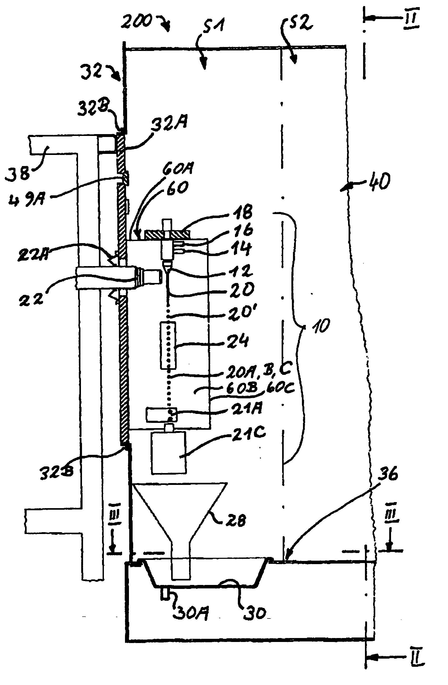
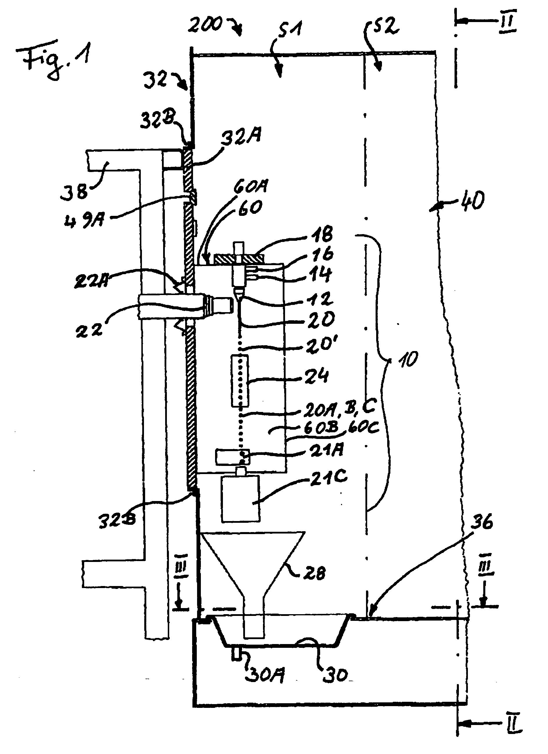
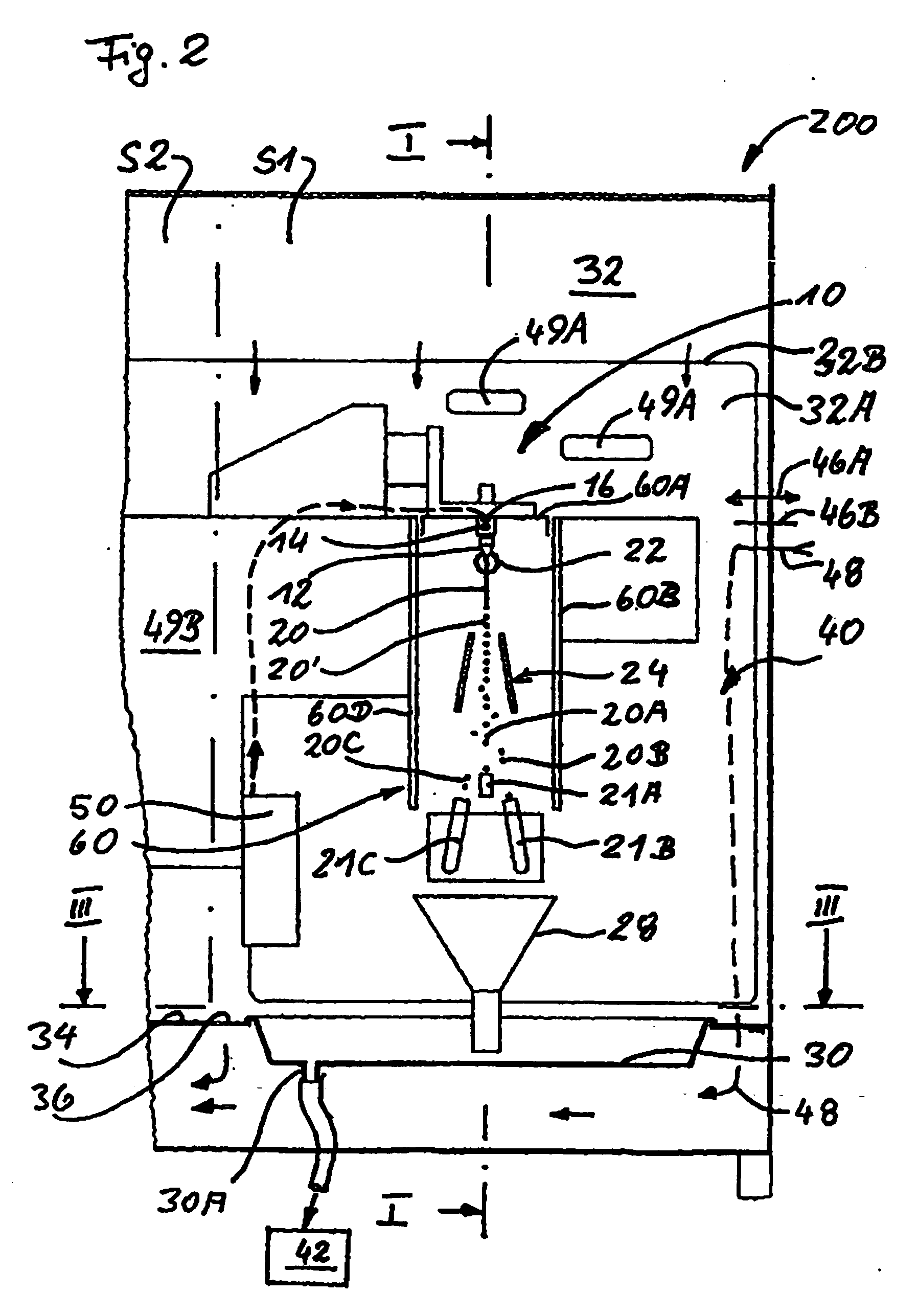
[0006]In order to attain this object is proposed a device with the features of claim 1 and a method with the features of claim 19. The invention is based on the basic idea of docking and functionally dividing a sorting system on a microbiological safety cabinet (msc) in such a way that the laminar HEPA-filtered supply air flow guided through the clean room is disturbed as little as possible and the required strict safety conditions for microbiological safety cabinets are followed. Safety cabinets are technical work appliances destined for activities with biological work materials and especially comply with the management criteria of national and international standards (BS 5726, DIN EN 12469, and NSF standard 49). According to the invention, the functional division of the sorting devic...


PUM


Abstract

The invention relates to the separation of microparticles by means of a nozzle (12) for the release of a separating stream (20), comprising at least one enveloping fluid and microparticles entrained Therein, with a vibration generator (18), for the dispersion of the separation flow (20) into a droplet flow (20′), with a deflector device (24), for separation of the droplet flow (20′) into a through flow (20A) and at least one side flow (20B, 20C, . . . ), depending on signals from an analytical device (38). Said analytical device (38) is provided for the analysis of the microparticles(s) contained in the droplets and to control the deflector device (24). Also provided is a protective chamber for product and personnel protection, in which at least the nozzle (12), the oscillation generator (18) and the deflector device (24) are arranged. The analytical device is arranged essentially outside the microbiological safety cabinet (200), whereby, according to the invention, the protective chamber is part of a microbiological safety cabinet (MSW 200), in particular with a laminar throughflow, with a clean chamber (34) and with a monitoring device (22), provided in a side wall, in particular in the back wall (32) of the microbiological safety cabinet (200), through which the signals of the microparticles arising from the separating stream (20) are supplied to the detectors of the analytical device (38), arranged outside the microbiological safety cabinet (200).

Description

TECHNICAL FIELD OF THE INVENTION[0001]The invention concerns a device for sorting fine particle materials, called in the following microparticles, with the features of the preamble of claim 1 as well as a method pursuant to claim 19. Sorting devices of this kind are used nowadays in so-called flow cytometry to sort biological materials, especially in the form of cells, such as, for example, lymphocytes or stem cells. For this purpose, a fluidic sorting stream is formed, which is formed in a nozzle as a fine fluid stream and is delivered by it. A vibration generator impinges the sorting stream in the area of the nozzle with a high-frequency vibration, which causes the sorting stream to exist only for a short distance as cohesive fluid stream and causes it to increasingly constrict in time with the vibrations at regular intervals until the sorting stream changes into a droplet stream. Individual droplets receive different electric charges from a measurement and evaluation unit in depe...

Claims


Application Information

Patent Timeline
Patent Type & Authority Applications(United States)
IPC IPC(8): B07B7/00B01L1/00
CPCG01N15/1459G01N2001/2223G01N2035/00277G01N2015/149G01N2015/0019
Inventor KIRSTEIN, UWELENNARTZ, KLAUS
Owner UNIV DUISBURG ESSEN
Why Eureka
Try Eureka