Electric motor for an air blowing device and air blowing device

an air blowing device and electric motor technology, applied in the direction of machines/engines, mechanical equipment, magnetic circuit shapes/forms/construction, etc., can solve problems such as affecting the operation of other electronic units, and achieve the effect of limiting the propagation of electromagnetic radiation

Inactive Publication Date: 2018-10-18
VALEO SYST THERMIQUES
View PDF6 Cites 10 Cited by
  • Summary
  • Abstract
  • Description
  • Claims
  • Application Information

AI Technical Summary

Benefits of technology

[0006]The aim of the present invention is to overcome at least some of the aforementioned disadvantages and to propose an electric motor and an associated air blowing device making it possible, in particular, to limit the propagation of electromagnetic radiation outside said motor.
[0008]In this manner, it is possible to easily position a shielding cap which limits the propagation of the electromagnetic radiation generated by the coils of the stator. More particularly, the shielding cap is, thus, arranged in immediate proximity to the stator thus allowing for better confinement of the electromagnetic radiation.
[0010]the mean for fixing comprises a first part placed on the shielding cap and a second part placed on the support; thus, the mean for fixing making it possible to fix the shielding cap to the support for said rotor and stator are distributed on each of said elements;
[0011]the first and second parts of said mean for fixing are integrated in said shielding cap and said support, respectively. In other words, each of the parts of said mean for fixing is formed directly in the shielding cap or the support for said rotor and stator. In other words, the first part of the mean for fixing forms an integral piece with the shielding cap and the second part of said mean for fixing forms an integral piece with said support. As a result, this avoids intermediate additional pieces, for example a bolt, in order to fix the shielding cap to the support for said rotor and stator;
[0012]the support for said rotor and for said stator and the shielding cap are electrically linked; this characteristic makes it possible to improve the effectiveness of said shielding cap in limiting the propagation of the electromagnetic radiation out from the electric motor;

Problems solved by technology

Moreover, a problem that exists with this type of motor is that, during use, electromagnetic radiation is generated, but it can disrupt the operation of other electronic units placed in proximity to said motor.

Method used


Image

  • Electric motor for an air blowing device and air blowing device
  • Electric motor for an air blowing device and air blowing device
  • Electric motor for an air blowing device and air blowing device

Examples


Embodiment Construction

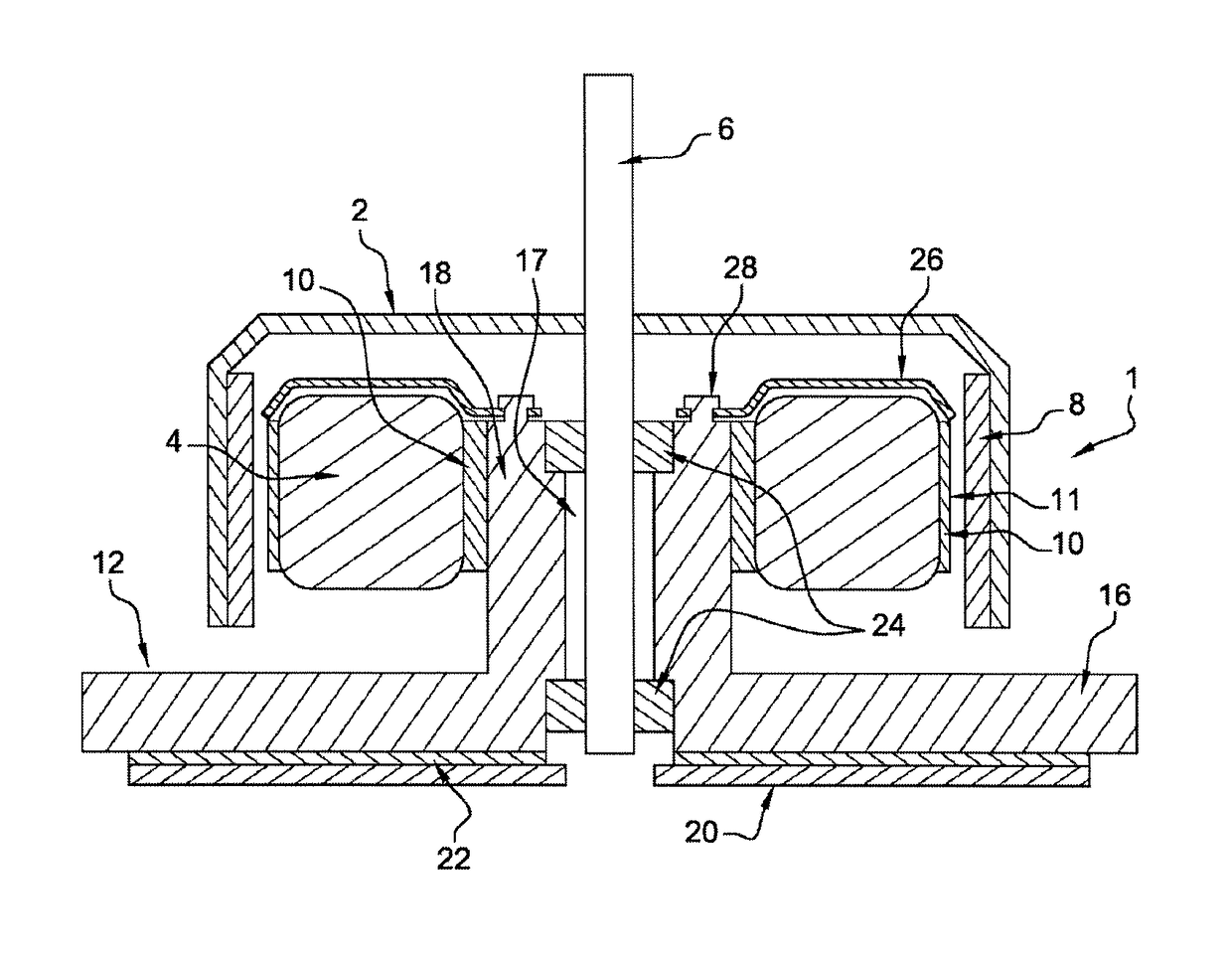
[0034]FIG. 1 illustrates a diagram of an electric motor according to the invention according to a sectional view. The electric motor 1 comprises a rotor 2 and a stator 4. The stator 4 has a substantially annular shape with a central wall delimiting the contour of an internal bore through which a transmission shaft 6 passes, which transmission shaft will be described at a later time. The stator 4 further includes one or more magnetic coils generating an electromagnetic field and metal plates 10 which extend substantially parallel to the axis of the transmission shaft 6. Each metal plate 10 is arranged such that a passage zone for the winding of the coil is formed between two adjacent metal plates 10. An electrically insulating plastic layer 11 can also be added to the metal plates 10 in order to insulate the metal plates from the coils or from a magnet 8 which will be described at a later time.

[0035]The rotor 2, arranged around the stator 4, carries at least one permanent magnet 8, t...


PUM


Abstract

Electric motor (1) for an air blowing device, comprising a rotor (2), a stator (4), a support (12) for said rotor (2) and said stator (4) able to dissipate heat and a screening cap (26), characterized in that the screening cap (26) is fixed to the support (12) of said rotor (2) and of said stator (4) by a fixing means (28). The invention also relates to an air blowing device comprising such an electric motor (1).

Description

TECHNICAL FIELD OF THE INVENTION[0001]The present invention relates to the field of electric motors, particularly those used for the air blowing devices of a motor vehicle heating, ventilation and / or air conditioning system (also known by the acronym “HVAC”).PRIOR ART[0002]A motor vehicle is commonly provided with a ventilation, heating and / or air conditioning device in order to regulate the temperature of an air flow delivered towards the inside of the passenger compartment of the vehicle. The device generally comprises a cover delimited by separations in which openings, including at least one air inlet and at least one air outlet, are organized.[0003]In a known manner, the cover houses an air blowing device or blower, in order to circulate the air flow from the air inlet towards the air outlet. The cover also houses heat treatment means for heating and / or cooling the air flow prior to the delivery thereof inside the passenger compartment.[0004]The blowers generally include electro...

Claims


Application Information

Patent Timeline
Patent Type & Authority Applications(United States)
IPC IPC(8): F04D25/06H02K11/22H02K11/01H02K1/18
CPCF04D25/064H02K11/022H02K11/01H02K1/187H02K11/40H02K3/24H02K21/22H02K9/227H02K11/0141H02K11/014
Inventor CAPOULUN, GEOFFROYGUIGOU, PASCAL
Owner VALEO SYST THERMIQUES
Why Eureka
Try Eureka