
Dipole flow driven resonators for fan noise mitigation

a technology of dipole flow and resonators, applied in the field of acoustic resonators, can solve the problems of axial turbomachinery noise, broadband noise, and tip clearance noise,

Active Publication Date: 2011-08-09
PENN STATE RES FOUND
View PDF18 Cites 19 Cited by
  • Summary
  • Abstract
  • Description
  • Claims
  • Application Information

AI Technical Summary

Benefits of technology

The present invention provides a dipole acoustic resonator configuration that can reduce the noise output of an axial fan. The resonators are placed on the rotor blades and act to attenuate the noise propagations in both directions. The resonators have openings that are positioned on the rotor side of the stator blades. The resonators can be tuned to the same or different frequencies to achieve maximum response. The fan system may also include a shroud with the resonators placed on its inner surface. The technical effect of this invention is to provide a quieter fan system with reduced noise output.

Problems solved by technology

Axial turbomachinery noise is prevalent in many products ranging from large scale turbofan engines and compressor / turbine arrays to HVAC systems and computer cooling fans.
For subsonic axial fans, broadband noise results primarily from turbulent boundary layer scattering over a blade's trailing edge (TE), tip clearance noise and, potentially, from stall.
Tonal noise results from rotor / stator interactions with time-invariant flow distortions and direct field interaction of rotor / stator blades.
When spectrally dominant, blade tones are of primary concern in noise control applications due to their particular annoyance.
However, difficulty in tuning the response of these interactions often limits their usefulness.
Few passive approaches have demonstrated the ability to reduce blade tone noise locally in the blade region with minimal impact on fan efficiency.
These approaches have proven effective in a laboratory setting, but are generally prohibitively expensive and potentially unreliable in most actual axial fan applications.
While this results in a reduced noise level in one (in this case, downstream) direction, it also may cause an increased noise level in the other (in this case, upstream) direction.

Method used


Image

  • Dipole flow driven resonators for fan noise mitigation
  • Dipole flow driven resonators for fan noise mitigation
  • Dipole flow driven resonators for fan noise mitigation

Examples


Embodiment Construction

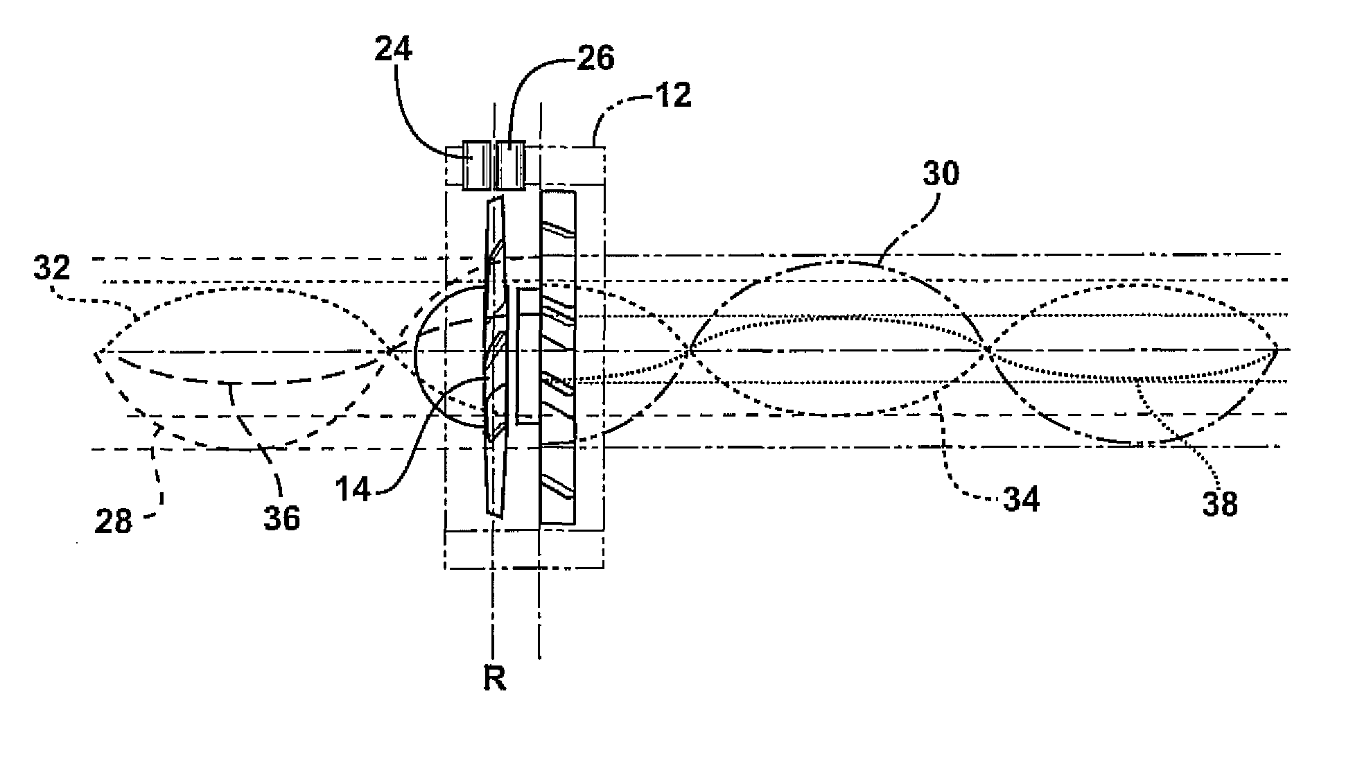
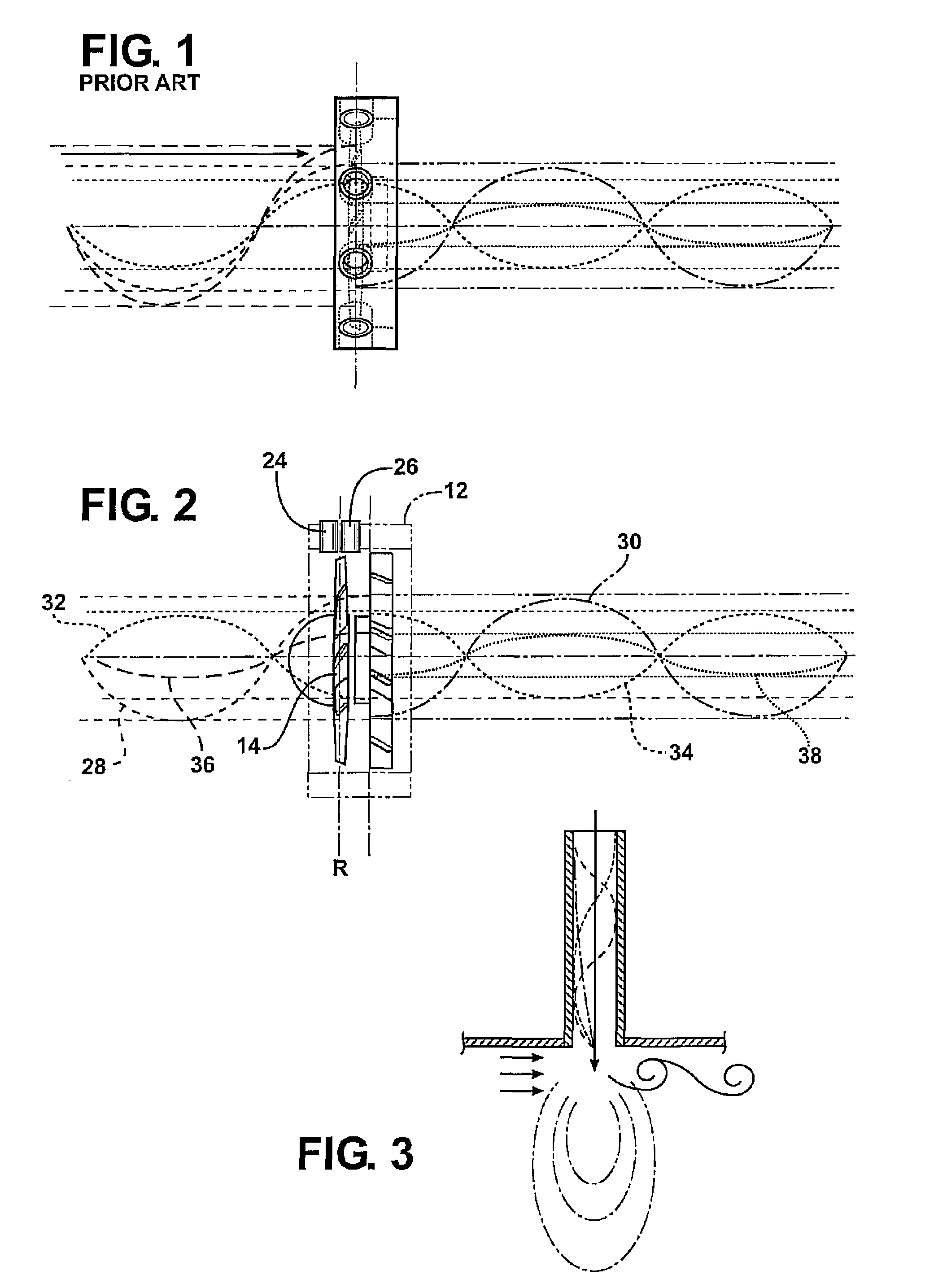
[0030]The present invention provides a dipole acoustic resonator configuration for use with or as part of a fan system so as to provide attenuation of bi-directional fan noise propagations, potentially locally canceling the entirety or a substantial portion of the tonal output of an axial fan.

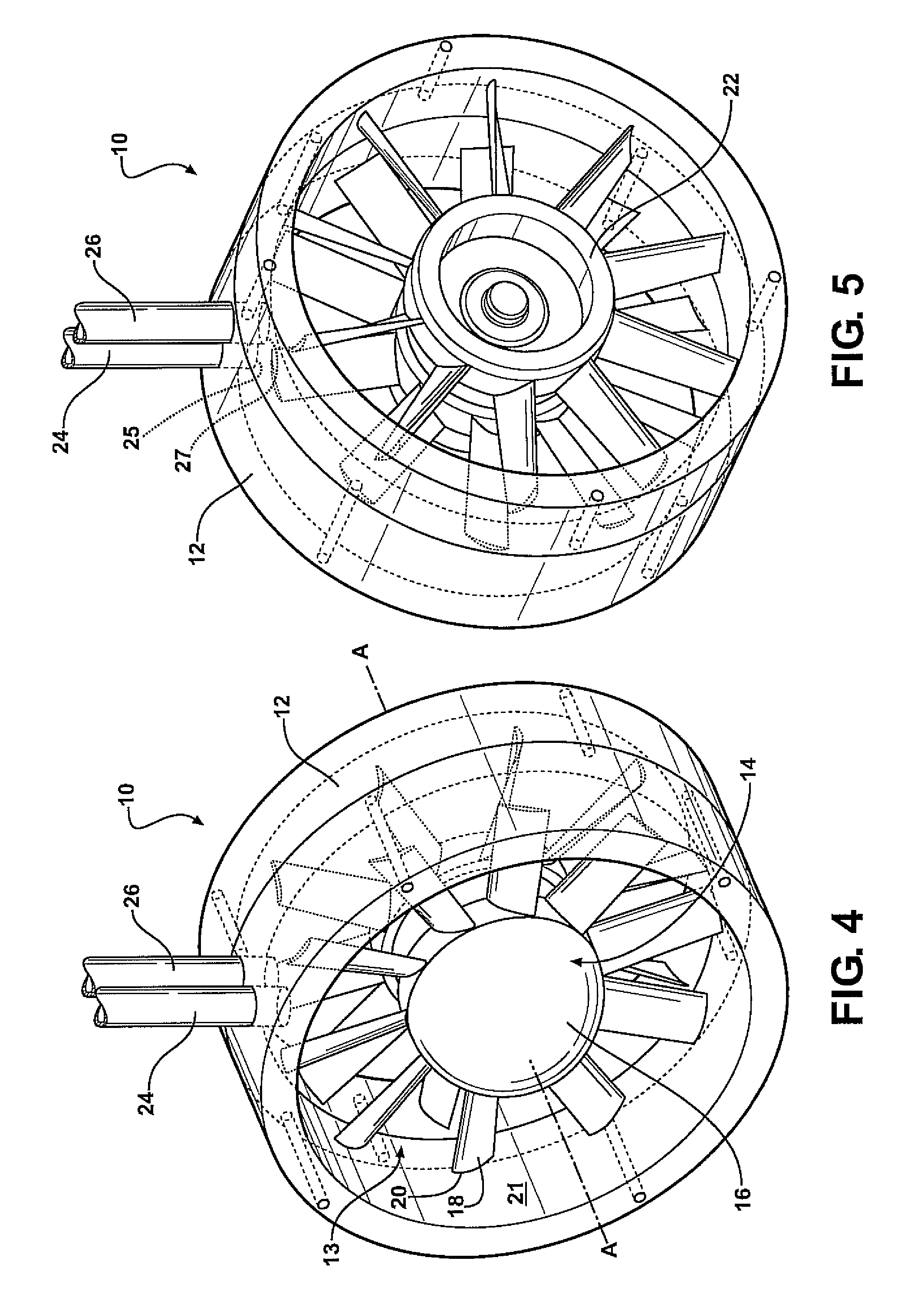
[0031]Referring to FIGS. 4 and 5, an axial fan system 10 according to an embodiment of the present invention includes a shroud 12 that generally defines a passage 13 having a fan axis A. A rotor 14 is disposed in the passage and rotates about the axis A. As shown, the rotor 14 has a central hub 16 and a plurality of rotor blades 18 extending outwardly from the hub 16 to tips 20 near an inner surface 21 of the shroud 12. The system 10 also includes a stator 22 that is adjacent the rotor 14. The stator 22 supports the rotor hub so that the rotor can rotate about the axis. The stator may take a variety of forms. In the illustrated embodiment, the stator 22 has a plurality of blades that extend bet...


PUM


Abstract

A fan system includes a rotor supported for rotation about a fan axis. The rotor has a central hub and a plurality of blades each extending outwardly from the hub to a tip. The rotor blades define a rotor plane perpendicular to the fan axis. A first acoustic resonator has an opening disposed on a first side of the rotor plane and a second acoustic resonator has an opening disposed on a second side of the rotor plane. The acoustic resonators are configured to provide a dipole resonator system operable to at least partially reduce a blade pass frequency tone in an upstream and a downstream direction simultaneously.

Description

CROSS REFERENCE TO RELATED APPLICATIONS[0001]This application claims priority to U.S. provisional patent application Ser. No. 61 / 061,352, filed Jun. 13, 2008 the entire content of which is incorporated herein by reference.FIELD OF THE INVENTION[0002]The present invention relates generally to acoustic resonators for use with fans.BACKGROUND OF THE INVENTION[0003]Axial turbomachinery noise is prevalent in many products ranging from large scale turbofan engines and compressor / turbine arrays to HVAC systems and computer cooling fans. Noise generated by turbomachinery has both broadband (due to the randomness of turbulent flow and its interaction with blade structures) and tonal components (due to periodic excitation of rotor blades and resonance sources). For subsonic axial fans, broadband noise results primarily from turbulent boundary layer scattering over a blade's trailing edge (TE), tip clearance noise and, potentially, from stall. Tonal noise results from rotor / stator interactions...

Claims


Application Information

Patent Timeline
Patent Type & Authority Patents(United States)
IPC IPC(8): F01N1/02
CPCF04D29/663F04D29/665G10K11/172
Inventor GORNY, LEE J.KOOPMANN, GARY H.CAPONE, DEAN E.
Owner PENN STATE RES FOUND
Learn More