
DC-offset eliminating method and receiving circuit

a technology of dc-offset and eliminating method, which is applied in the direction of dc level restoring means or bias distort correction, phase-modulated carrier systems, baseband system details, etc., can solve problems such as inevitability, inaccurate demodulation and decoding, and degrade stability, so as to reduce the follow-up speed and reduce power consumption , the effect of reducing the dc-offset follow-up speed

Inactive Publication Date: 2006-05-23
NEC CORP
View PDF6 Cites 7 Cited by
  • Summary
  • Abstract
  • Description
  • Claims
  • Application Information

AI Technical Summary

Benefits of technology

[0040]According to the present invention, there is provided a receiving circuit with a DC-offset eliminating circuit to find DC-offset values contained in a receiving signal, an AID converting circuit and previously located circuits so as to automatically eliminate these DC-offset values. In the receiving circuit, the DC-offset eliminating circuit has a variable follow-up speed. The follow-up speed is reduced at a time of receiving a preamble pattern in which a DC offset is deviated from DC-offset values compared with when performing reception of normal data. It is a characterizing feature of the present invention that the deviation of a DC offset from DC-offset values which have been calculated is avoided.
[0041]Specifically, the DC-offset eliminating circuit includes means for changing the coefficient α to determine the DC-offset follow-up speed. The circuit changes the coefficient α to a smaller value or 0 in a case where a signal showing a detection that a reception is ceased, is received from a signal-end detecting circuit, or in a case where a signal for partly turning off the circuits for the reduction of power consumption is received from a control circuit, if the received frame is not destined for the receiver itself. The circuit remains the coefficient α to a smaller value immediately after the reception is resumed. Additionally, the circuit returns the coefficient α to the normal value in response to the reception of a signal showing that an alignment signal is detected immediately after a preamble portion. It is possible to reduce the DC-offset follow-up speed as much as possible at the time when the preamble portion is received, thereby avoiding the DC-offset deviation caused by the preamble patterns.
[0042]The receiving circuit according to the present invention detects the beginning of the intermittent reception so as to reduce the follow-up speed, even when the intermittent reception prevents the receiving circuit from receiving the signal-end indication due to systematic limitations. As a result, it is possible to avoid the deviation of the DC-offset value caused by the preamble patterns received while the intermittent reception is performed.

Problems solved by technology

However, if it is larger, stability will be degraded.
Hence the accurate DC offset can not be maintained for the following data, resulting in inaccurate demodulation and decoding.
Such a problem is inevitable due to the system configuration.
This results in a problem of inaccurate demodulation and decoding.

Method used


Image

  • DC-offset eliminating method and receiving circuit
  • DC-offset eliminating method and receiving circuit
  • DC-offset eliminating method and receiving circuit

Examples


Embodiment Construction

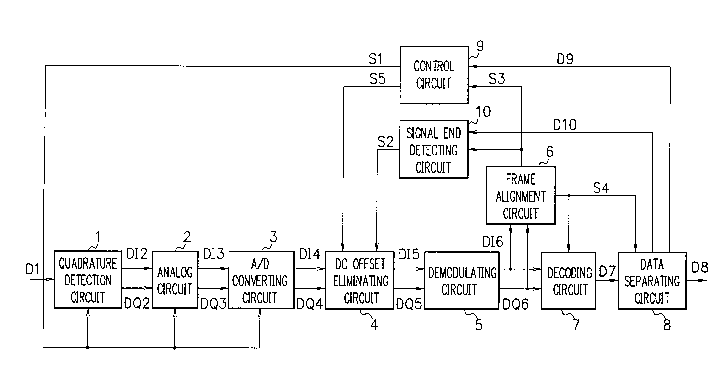
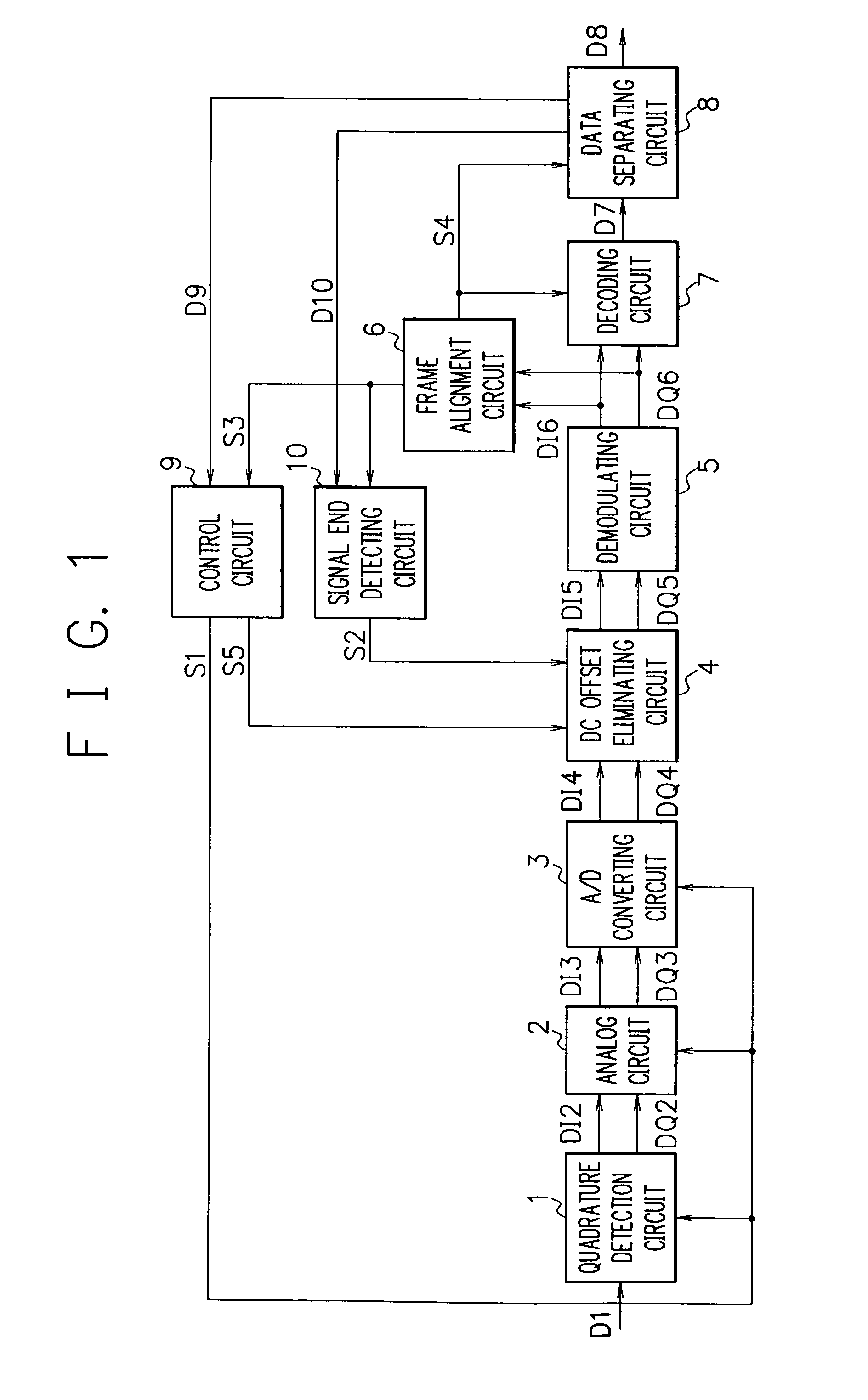
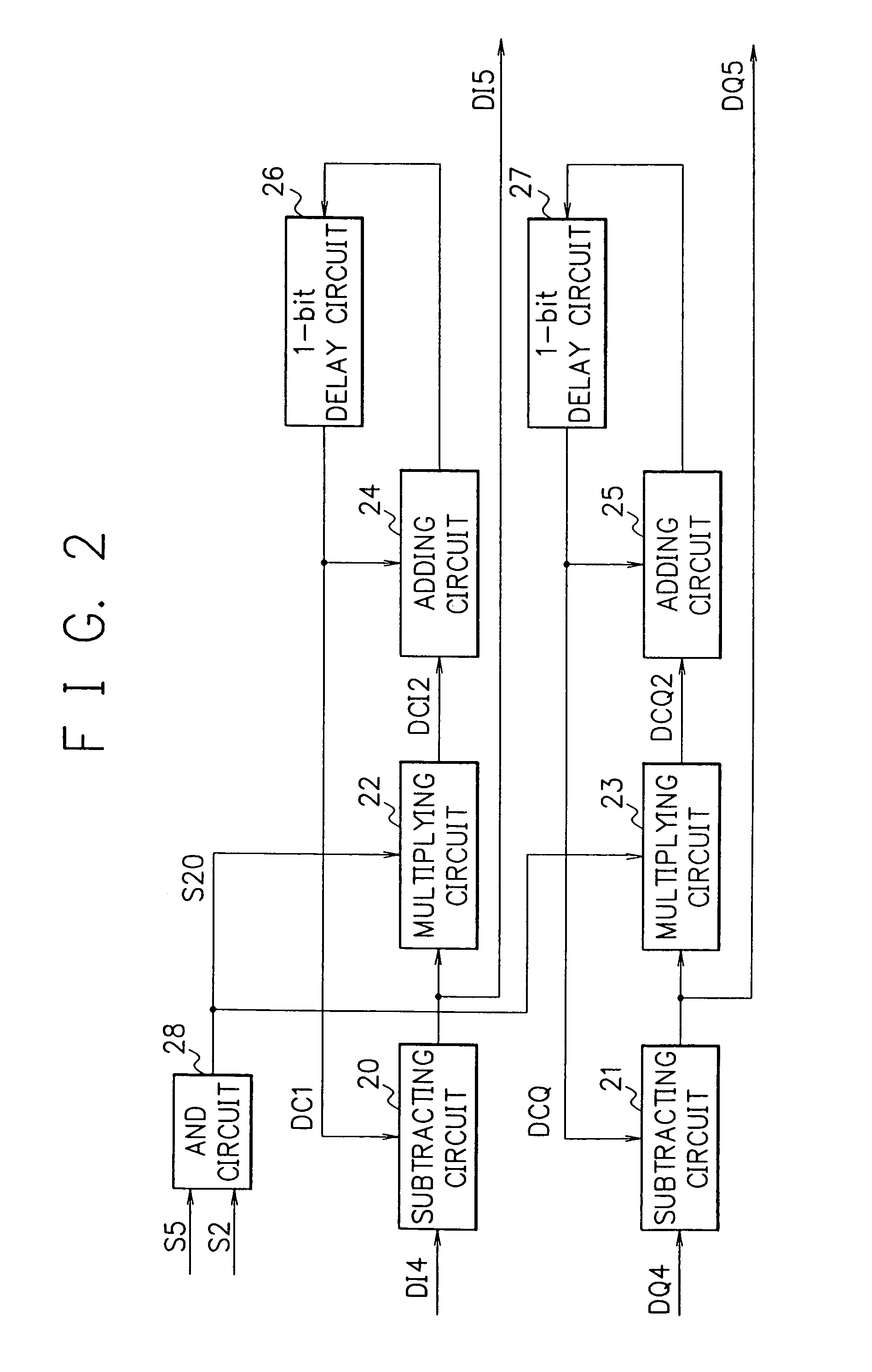
[0053]FIG. 1 is a block diagram of a receiver according to an embodiment of the present invention. FIG. 2 is a block diagram illustrating an internal configuration of a DC-offset eliminating circuit 4 as shown in FIG. 1. It should be noted that circuits 1 to 3, 5 to 8, and 10 as shown in FIG. 1 and the operations thereof are identical with those circuits as shown in FIG. 4 with respect to the prior art. Circuits 20 to 27 of FIG. 2 and the operations thereof are also the same as those circuits as shown in FIG. 5 with respect to the prior art.

[0054]Furthermore, signals handled in the present embodiment form frame structures as shown in FIGS. 6 and 7. These signals are received by a plurality of receivers.

[0055]Each of the receivers initially receives all frames (for example, frames 0 to 255), then a control circuit 9 of the receiver analyzes data D9 associated with a control portion (CONT) of the received frame which has been separated by a data separating circuit 8. With this analysi...


PUM


Abstract

A DC-offset eliminating circuit changes a coefficient α for determining a DC-offset follow-up speed. The coefficient α is changed to a smaller value or 0 in a case where a signal showing a detection that a reception is ceased, is received from a signal-end detecting circuit, or in a case where a signal for partly turning off the circuits for the reduction of power consumption is received from a control circuit, if the received frame is not destined for the receiver itself. The circuit remains the coefficient α to a smaller value immediately after the reception is resumed. Additionally, the circuit returns the coefficient α to the normal value in response to the reception of a signal showing that an alignment signal is detected immediately after a preamble portion. The circuit then reduces the DC-offset follow-up speed as much as possible at the time when the preamble portion is received, thereby avoiding the DC-offset deviation caused by the preamble patterns.

Description

BACKGROUND OF THE INVENTION[0001]The present invention relates to a DC-offset eliminating method and a receiving circuit capable of eliminating a DC-offset component contained in a baseband signal after quadrature detection is performed.DESCRIPTION OF THE RELATED ART[0002]FIG. 4 is a block diagram showing a receiving circuit with a prior-art DC-offset eliminating circuit. The receiving circuit deals with signals forming frame structures as shown in FIGS. 6 and 7, and these signals are received by a plurality of receivers. Each of the receivers analyzes control portions (CONT) 62 and 72 of the frame as shown in FIGS. 6 and 7, thus deciding whether or not the frame is destined or self-addressed for the receiver itself.[0003]Alignment portion (UW) 61 and 71 of the frame includes 20- to 40-bit fixed patterns which indicate boundaries of the frames, and the portion is generally known as a unique word (UW). The control portion (CONT) contains the frame numbers which are cyclic at predeter...

Claims


Application Information

Patent Timeline
Patent Type & Authority Patents(United States)
IPC IPC(8): H04J11/00H04J3/06H04L27/22H04L25/06
CPCH04L25/061
Inventor MURAOKA, SHINYA
Owner NEC CORP
Learn More