
Method, system, and program for implementing a remote method call

a remote method and method technology, applied in the field of method, system and program for implementing a remote method call, can solve the problems of increasing software development costs, adversely affecting network performance, and inability to communicate with any other server or computer

Active Publication Date: 2006-05-23
TWITTER INC
View PDF20 Cites 11 Cited by
  • Summary
  • Abstract
  • Description
  • Claims
  • Application Information

AI Technical Summary

Problems solved by technology

This requirement that the calls to the proxy object include “guarding” code to handle the RMI specific exceptions increases software development costs because every caller that invokes methods on the stub object must be additionally coded to handle RMI exceptions.
Further, client-server applications that make frequent calls to the stub objects on the client that require communication with the server may generate significant network traffic that may adversely effect network performance.
Thus, within the current RMI framework, unsigned applets can only communicate with the server from which the applet was downloaded and launched, and cannot communicate with any other servers or computers.
However, in all cases, the unsigned applet cannot interact with servers other than the server from which the applet was downloaded, even if such direct applet-to-server interaction would be the most efficient design.
Still further, if a developer incorporates the RMI framework into their programming environment, then migrating to a different communication protocol that may be more suitable than RMI would prove difficult because the developer would have to recode all the client callers that invoked methods on the RMI stub object to remove the RMI specific exception handling code from such callers and then incorporate any specific error exception handling code required by the new protocol.
This process of having to recode all classes and callers that previously used the RMI framework and called the RMI stub file could substantially increase the cost and time commitment needed to switch to a different client-server communication protocol.

Method used


Image

  • Method, system, and program for implementing a remote method call
  • Method, system, and program for implementing a remote method call
  • Method, system, and program for implementing a remote method call

Examples


Embodiment Construction

[0023]In the following description, reference is made to the accompanying drawings which form a part hereof and which illustrate several embodiments of the present invention. It is understood that other embodiments may be utilized and structural and operational changes may be made without departing from the scope of the present invention.

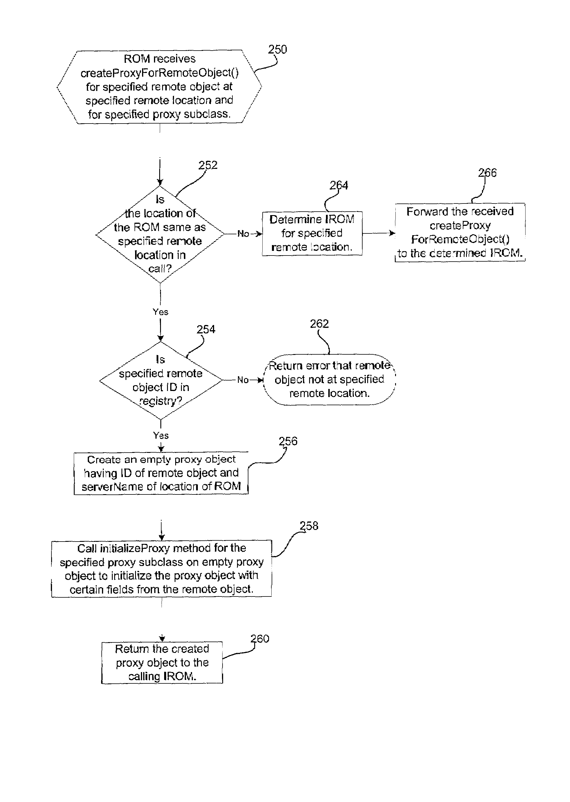
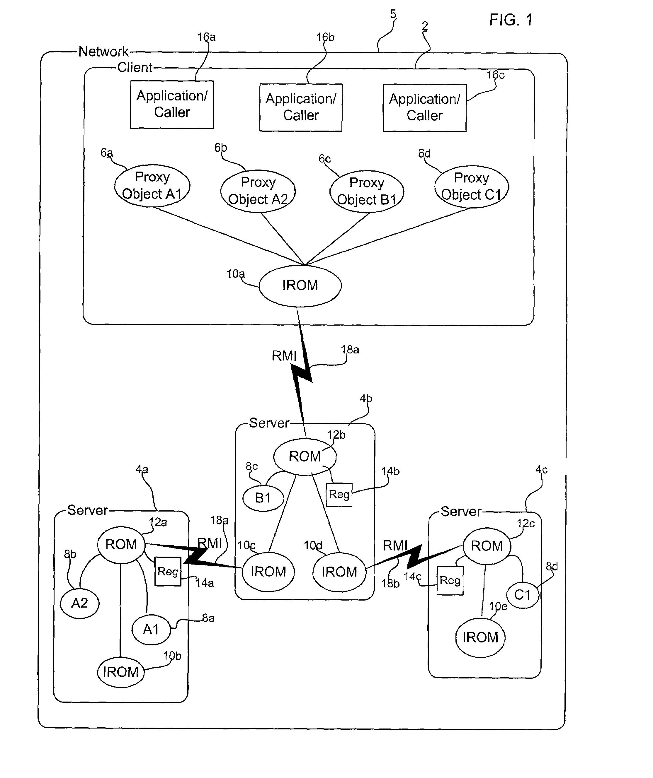
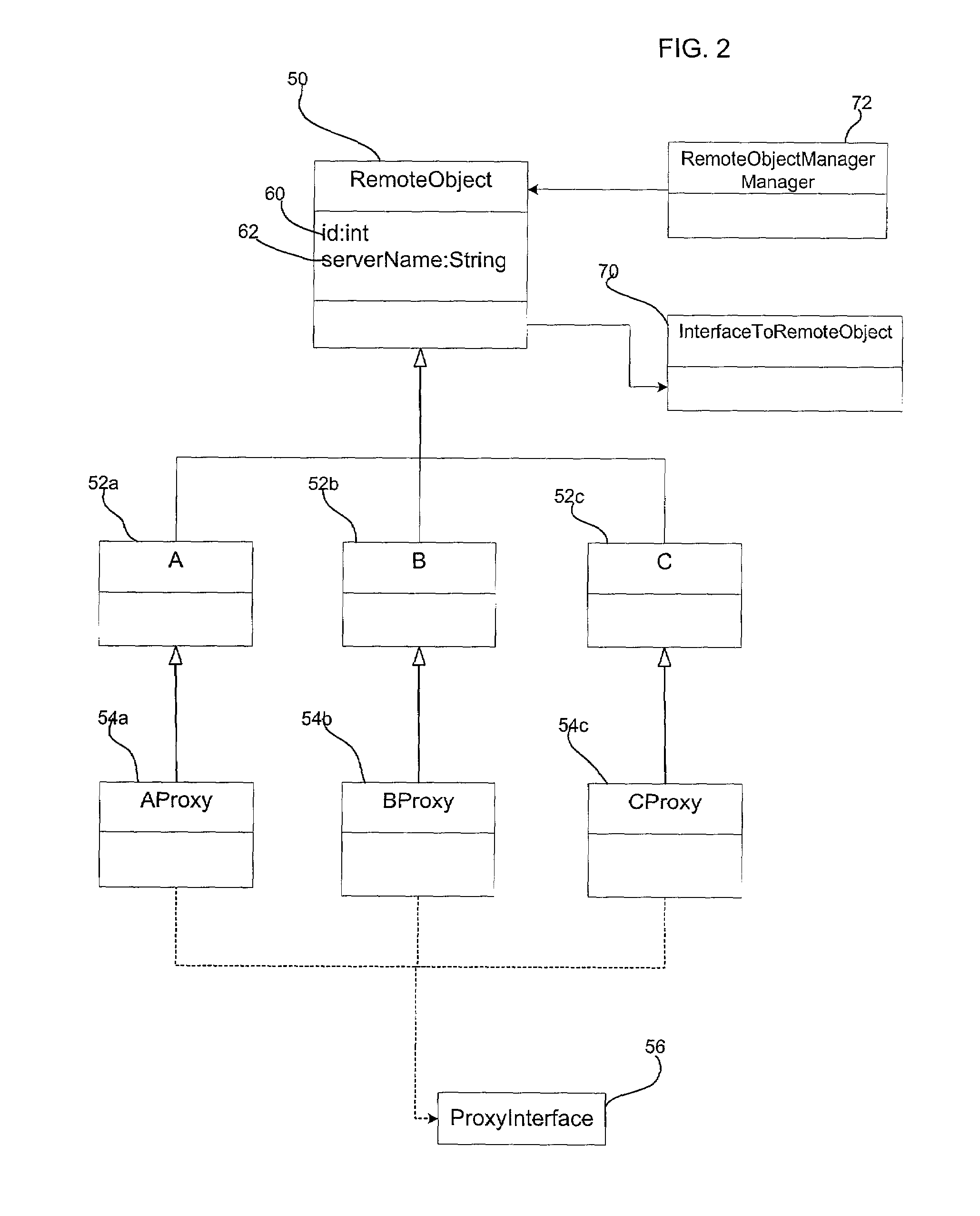
[0024]FIG. 1 illustrates a computing environment in which aspects of the invention are implemented. A client system 2 and servers 4a, 4b, and 4c communicate over a network 5, which may comprise any network known in the art, e.g., a Local Area Network (LAN), Wide Area Network (WAN), Storage Area Network (SAN), the Internet, an Intranet, etc. The client 2 includes a plurality of proxy objects 6a, 6b, 6c, 6d instantiated for remote objects 8a, 8b, 8c, and 8d, respectively, on the servers 4a, 4b, 4c. The client 2 and the servers 4a, 4b, and 4c each include an Interface Remote Object Manager (IROM) 10a, 10b, 10c, 10d, 10e and the servers 4a, 4b, and 4c f...


PUM


Abstract

Provided is a computer implemented method, system, and program for implementing for implementing a remote method call. Remote objects and at least one proxy object are generated, where each proxy object corresponds to one remote object. Data from the remote object is included into the proxy object. A call to a method on one proxy object is processed and the method is executed. The method is one of a plurality of methods, wherein at least one of the plurality of methods comprises a local method including code to perform method operations on the proxy object without going to the remote object and at least one other of the plurality of methods comprises a remote method including code to perform method operations on the remote object.

Description

BACKGROUND OF THE INVENTION[0001]1. Field of the Invention[0002]The present invention relates to a method, system, and program for method, system, and program for implementing a remote method call in a network environment including a client and server systems.[0003]2. Description of the Related Art[0004]The Java** Remote Method Invocation (RMI) protocol and other communication protocols, such as the Simple Object Access Protocol (SOAP), provides a framework in which objects on separate computers may communicate over a network. In the Java RMI framework, an object on a server is represented on a client system by a stub or proxy object. Applications running on the clients can call remote interfaces on the stub object that has the same set of remote interfaces defined by the remote object class. The stub object carries out the method call on the remote object. When a stub method is invoked, the stub object initiates a connection with the remote Java Virtual Machine (JVM) containing the...

Claims


Application Information

Patent Timeline
IPC IPC(8): G06F9/44G06F9/46
CPCG06F9/548
Inventor BURTON, DAVID ALANMORTON, ROBERT LOUISSTEFFENS, GARY WILLIAM
Owner TWITTER INC
Learn More