
Displacement device

a technology of displacement device and displacement shaft, which is applied in the direction of coupling-brake combination, vehicle arrangement, vehicle components, etc., can solve the problems of stepping transfer or change of direction of torque on the drive side, detrimental reversal play, noticeable detrimental effect, etc., and achieve reliable force and torque transfer

Inactive Publication Date: 2006-05-30
BROSE FAHRZEUGTEILE GMBH & CO KG
View PDF14 Cites 8 Cited by
  • Summary
  • Abstract
  • Description
  • Claims
  • Application Information

AI Technical Summary

Benefits of technology

[0007]The object of the present invention is therefore to provide a displacement device with optimum torsion angle play between a drive element, an output element and a load torque block which on the one hand is restricted to a minimum and on the other ensures a reliable force and torque transfer and which during assembly requires no adjustment and even after long term use requires no adjustment of the torsion angle play.
[0008]According to the invention a play compensating device which balances the torsion angle play between the drive element, output element and the load torque block, is mounted between the drive element and the load torque block or between the output element and the load torque block so that the functionally-conditioned torsion angle play between the drive element and the load torque lock or between the load torque lock and the output element is set and adjusted automatically. An automatic setting of the optimum torsion angle play thereby takes place taking into account the tolerances of the component parts and the adjustment is carried out taking into account the wear on the component parts so that a minimum idling stroke is ensured during operation and a high functional reliability of the displacement device is ensured taking into account the unavoidable wear. The manufacture of the individual component parts is thus considerably more economical, assembly of the displacement device is simplified and rejects are restricted to a minimum.
[0009]The load torque lock preferably has at least two locking elements mounted in a cylindrical displacement housing, with the clamping faces of the locking elements acting with predetermined pretension on the displacement housing under the action of the play compensating device which is mounted at least in part between opposing expanding faces of the locking elements and presses these locking elements apart from each other. Torque introduced on the output side thereby increases the bearing force of the clamping faces and thus of the locking elements against the displacement housing.
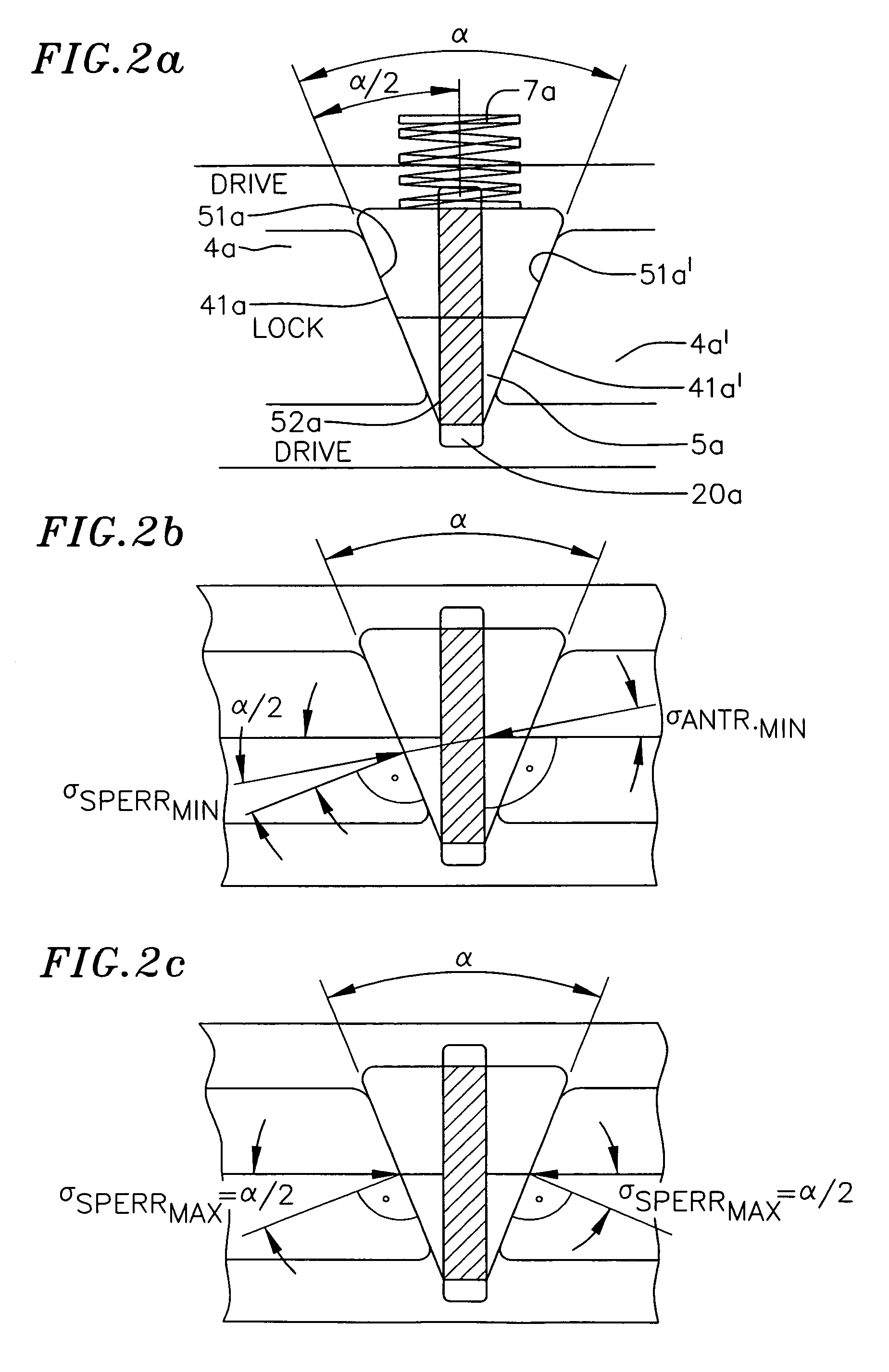
[0012]In order to ensure that the wedge on the one hand in the absence of any drive torque engenders the optimum setting and adjustment and does not hinder the movement of the locking elements, but on the other hand in the event of torque on the drive side is not radially displaced by the locking elements, and in order to keep the system able to function in the widest possible range, the material matching of the expanding faces and of the wedge faces on the one hand and of the active faces of the wedge guide and the slide guide of the drive element on the other hand is predetermined so that with the absence of drive torque the expanding faces can move the wedge against the action of the spring, but in the event of load on the drive side the wedge is held in its position. This is caused for example by a small friction value between the wedge faces and the expanding faces as well as by a high friction value between the guide face of the wedge and the slide guide of the drive element.
[0015]In order to produce a defined spot or linear contact between the wedge and the expanding faces of the locking elements, the expanding faces of the locking elements or the wedge faces are formed ball-shaped so that the slide action is minimal as a result of the slight friction of the surfaces which slide on each other and thus easy adjustment is guaranteed.

Problems solved by technology

Since the position of the locking elements of the load torque lock changes through tolerances and wear as a result of high flat surface pressures, in order to reach the required functional reliability of the known displacement device it is necessary to incorporate a large play so that during functioning a torsion angle play is present between the interengaging elements without which a stepped transfer or change of direction of the torques on the drive side is not possible.
Opposite this however too much torsion angle play, particularly in the case of a stepped transfer of the torque on the drive side, has a noticeable detrimental effect since the torsion angle play causes a correspondingly large idling path or idling stroke of the drive element.
Furthermore too much torsion angle play can lead, when reversing the movement, to a detrimental reversal play and to inaccurate handling.
The assembly of the individual component parts which are provided with small tolerances is therefore expensive since the component parts which are to be connected together have to be positioned very precisely relative to each other.

Method used


Image

  • Displacement device
  • Displacement device
  • Displacement device

Examples


Embodiment Construction

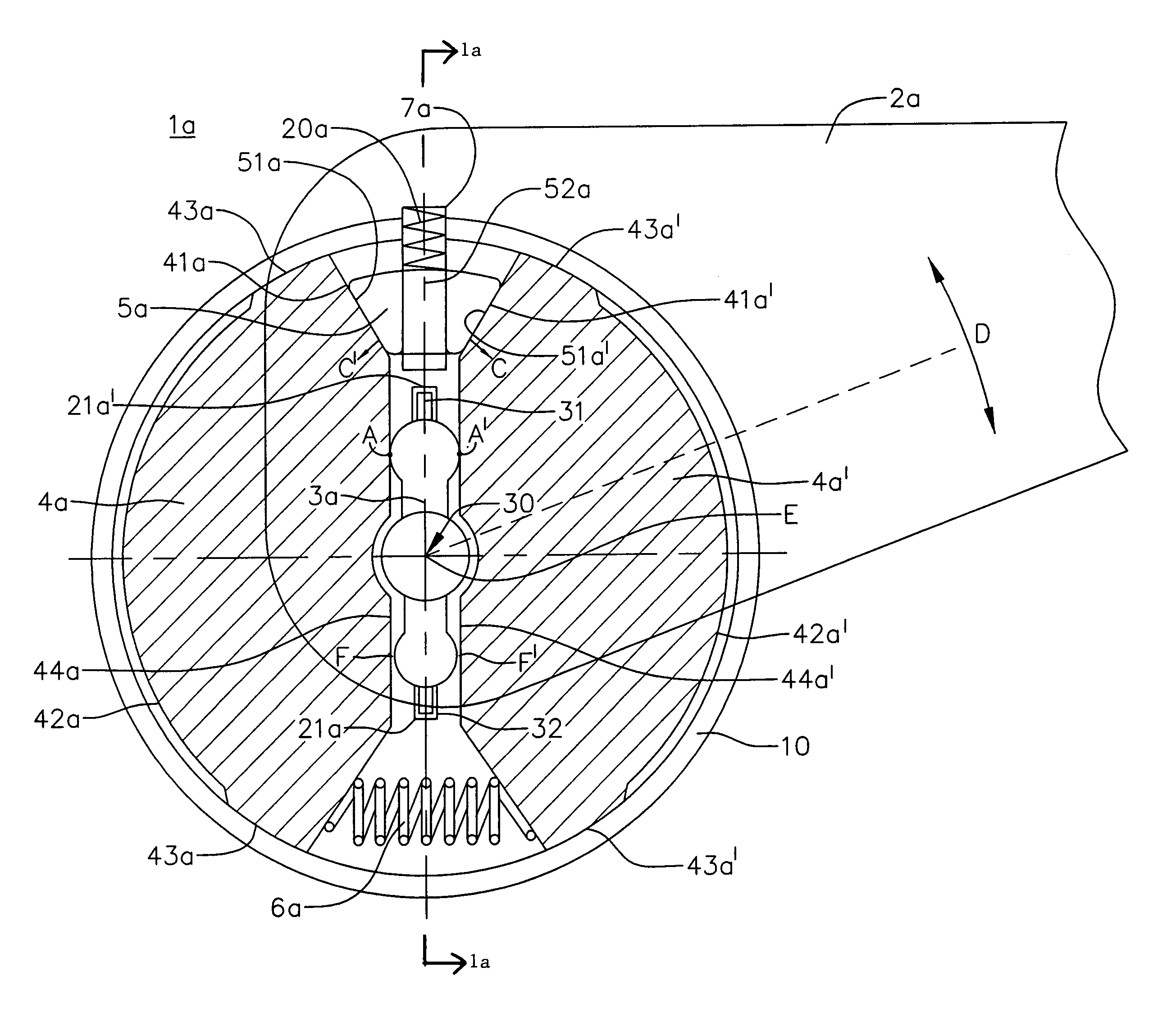
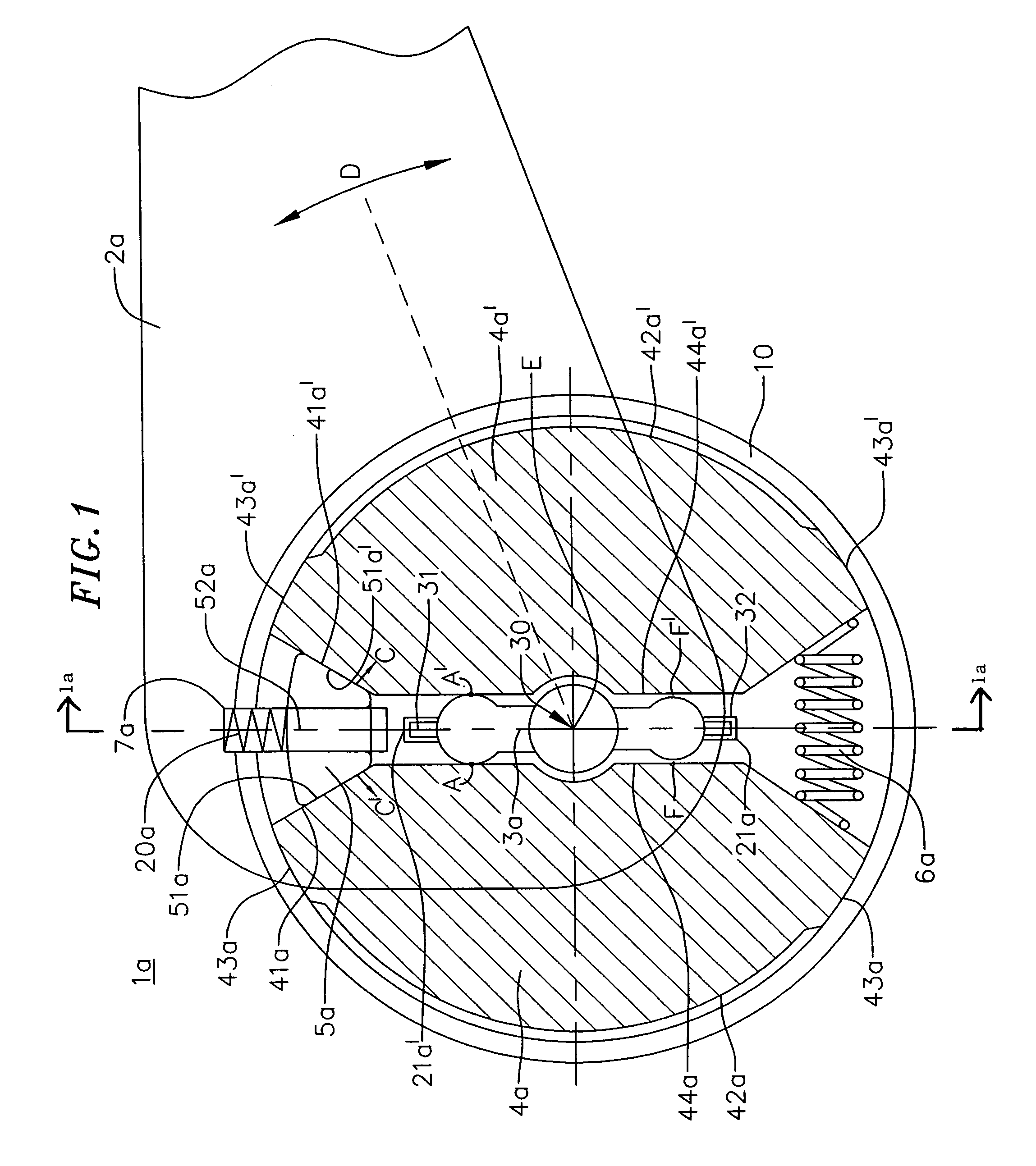
[0032]FIG. 1 shows a front sectional view through a double-sided acting displacement device 1a with a displacement housing 10 in which the functional parts of a load torque lock are mounted with automatic play compensation. FIG. 1a shows a side sectional view. A drive element formed as a drive lever 2a is mounted rotatable about an output axle 30. The output axle 30 includes an axis E about which the drive lever rotates in direction D. The output axle 30 is connected to an output element 3a. Between the drive element 2a and the output element 3a there are locking elements 4a and 4a′ formed as segments and adjoining the cylindrical inner face of the displacement housing 10 with a part of their peripheral faces 42a, 42a′ which are formed as locking faces 43a and 43a′.

[0033]The opposing expanding faces 41a, 41a′ of the locking elements 4a and 4a′ are adjoined by wedge faces 51a and 51a′ of a wedge 5a which causes an automatic play compensation. The wedge 5a is mounted with a wedge gui...


PUM


Abstract

A displacement device for producing a rotational movement with an output element adjustable in angle by operating a drive element. A load torque lock mounted between the drive element and the output element blocks, with force locking connection, torque introduced on the output side and transfers torque introduced on the drive side to the output element. Between the drive element and the load torque lock and / or between the output element and the load torque lock is a play compensating device which compensates the torsion angle play between the drive element, the output element and the load torque lock. The displacement device is used in particular for window lifters or seat adjusters of vehicles.

Description

CROSS-REFERENCE[0001]This application claims priority of German Application No. 199 26 994.7 filed Jun. 8, 1999. This application is also a continuation of patent application Ser. No. 09 / 592,485, filed Jun. 8, 2000, now abandoned the disclosure of which is incorporated fully herein by reference.BACKGROUND OF THE INVENTION[0002]The invention relates to a displacement device.[0003]From DE 41 20 617 C2 a displacement device is known which has a load torque lock with which torque on the drive side is transferred in both directions to an output element while torque on the output side is blocked in both directions by the load torque lock and the force is introduced into a displacement housing and is consequently not transferred to the drive element.[0004]Between the drive element and the load torque lock the torque on the drive side is transferred by means of elements which engage in each other with keyed engagement. Since the position of the locking elements of the load torque lock chang...

Claims


Application Information

Patent Timeline
Patent Type & Authority Patents(United States)
IPC IPC(8): B60N2/02B60N2/90
CPCB60N2/444B60N2/938
Inventor SCHECK, GEORGSCHUMANN, PETER
Owner BROSE FAHRZEUGTEILE GMBH & CO KG
Learn More