Twin-wire belt press

a belt press and twin-wire technology, applied in the direction of press section, separation process, filtration separation, etc., can solve the problem of generating a relatively large flow of white water that cannot be completely removed from the web, and achieve the effect of reducing production costs, improving reliability, and reducing production costs

Inactive Publication Date: 2006-05-30
VALMET TECH INC
View PDF15 Cites 19 Cited by
  • Summary
  • Abstract
  • Description
  • Claims
  • Application Information

AI Technical Summary

Benefits of technology

[0004]The object of the present invention is to provide a simpler, smaller, cheaper and more reliable twin-wire belt press than traditional belt presses.
[0005]This object is obtained by a twin-wire belt press of the kind described wherein the roll arrangement comprises at least one perforated hole roll that presses against the wire belts, whereby water that is pressed by the hole roll out of the web between the wire belts is at least partly drained through the hole roll. This effectively prevents rewetting of the web with white-water, which results in a reduction of the number of rolls in the twin-wire belt press. The expression “hole roll” is intended to mean a pressure roll with perforations in its mantle. For example, the perforations can communicate with outlet channels in the press roll. White water from the web is thus evacuated through the perforations and away from the wire belts.
[0007]According to a preferred embodiment of the invention the roll arrangement comprises two press rolls, a first press roll and a second press roll situated after the first press roll, as seen in the direction of movement of the wire belts. These press rolls press the two wire belts in the sections of the paths against the hole roll, so that the wire belts, in part, enclose the hole roll. Normally, there is no need for additional rolls for most applications, which makes this embodiment of the twin-wire belt press according to the invention particularly advantageous. Thus, the need for maintenance is reduced due to the fact that few roll bearings and hydraulic components are needed. In addition, the twin-wire belt press according to the invention will be substantially smaller than a conventional press of the same capacity. A further advantage is that the lifetime of the wire belts will be longer than wire belts used in prior art twin-belt presses, since the number of load cycles on the wire belts will be fewer with fewer rolls.

Problems solved by technology

A drawback of the known twin-wire belt press according to WO 99 / 01609, however, is that the press roll nip directly after the dewatering tables generates a relatively large flow of white water that cannot completely be removed from the web.

Method used


Image

  • Twin-wire belt press
  • Twin-wire belt press

Examples


Embodiment Construction

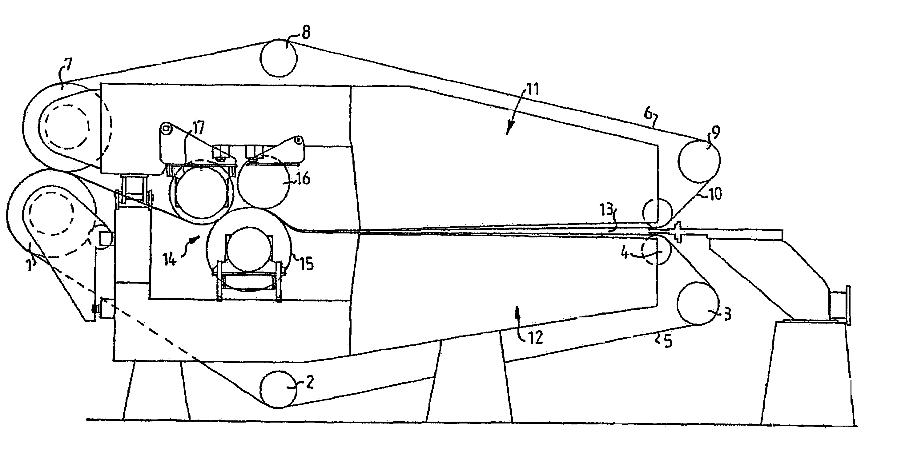
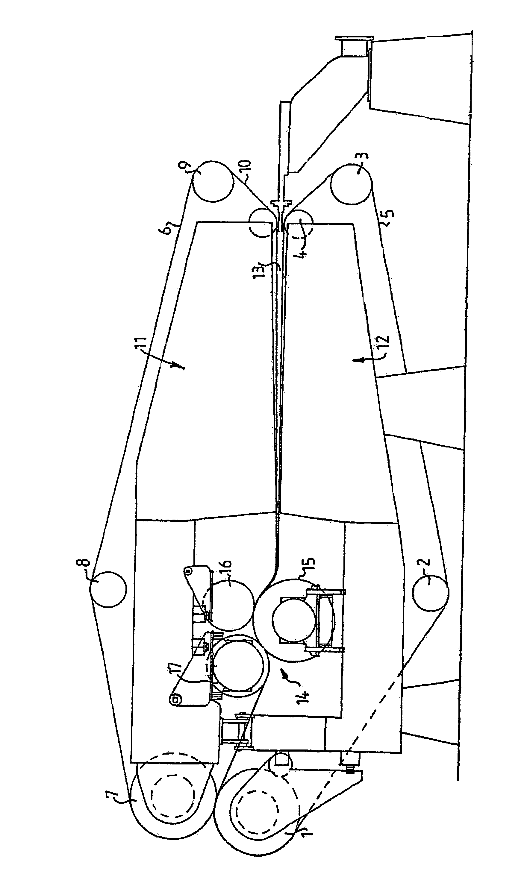
[0011]FIG. 1 shows a twin-wire belt press in accordance with the present invention comprising four lower rolls: a drive roll 1, a control roll 2, a tensioning roll 3 and a wire belt guide roll 4. An endless lower wire belt 5 runs in a path around the lower rolls 1–4. In a corresponding manner, an upper endless wire belt 6 runs in a path around four upper rolls: a drive roll 7, a control roll 8, a tensioning roll 9 and a wire belt guide roll 10. Between the rolls 1 and 7, and between the rolls 4 and 10 there are sections of the paths running substantially in parallel with each other, wherein the lower wire belt 5 and the upper wire belt 6 co-operate with each other for dewatering a fiber suspension between the wire belts 5,6 during displacement of the wire belts 5,6. An upper dewatering table 11 supporting the upper wire belt 6 and a lower dewatering table 12 supporting the lower wire belt 5 form a wedge-shaped pressure space 13 between the wire belts in the sections of the paths.

[00...


PUM

PropertyMeasurementUnit
pressureaaaaaaaaaa
pressing forceaaaaaaaaaa
elasticaaaaaaaaaa

Abstract

A twin-wire belt press is disclosed for dewatering a fiber suspension and forming a continuous web of the fiber suspension. The twin wire belt includes a plurality of upper and lower rolls, a perforated roll and endless upper and lower wire belts. Dewatering tables are used to support the endless upper and lower wire belts and form a wedge-shaped pressure space between the endless upper and lower wire belts for initially pressing and dewatering the fiber suspension and forming a web therebetween. Roll members, including at least two press rolls which form press roll nips with the perforated roll and another roll, press and dewater the web between the endless upper and lower wire belts.

Description

[0001]The present invention relates to a twin-wire belt press for dewatering of a fiber suspension and forming of a continuous web thereof, comprising lower rolls, an endless lower wire belt running in a path around the lower rolls, upper rolls, and an endless upper wire belt running in a path around the upper rolls. The two wire belts co-operate with each other along sections of the paths that run substantially in parallel with each other for dewatering of the fiber suspension between the wire belts during displacement thereof. The twin-wire belt press further comprises two dewatering tables supporting the respective wire belts in the sections of the path and forming a wedge-shaped pressure space between the wire belts for initially pressing and dewatering the fiber suspension, whereby a web is formed between the wire belts, and a roll arrangement situated after the dewatering tables in the sections of the paths, as seen in the direction of movement of the wire-belts, for finally p...

Claims


Application Information

Patent Timeline
Patent Type & Authority Patents(United States)
IPC IPC(8): B30B9/24B01D33/052D21F1/80D21F3/04D21F3/00D21F9/02
CPCD21F3/04D21F1/80
Inventor ODMARK, LEIFOLSSON, GORANULLMAR, MATS
Owner VALMET TECH INC
Why Eureka
Try Eureka