Electric drop bolt with slidable drive mechanism

a technology of electric motor and drive mechanism, which is applied in the field of improved electric motor driven drop bolts, can solve the problems of lock jamming, bolt jamming in the hole, and inability to be withdrawn, and achieve the effect of facilitating engagemen

Active Publication Date: 2006-05-30
ASSA ABLOY AUSTRALIA PTY LTD
View PDF5 Cites 32 Cited by
  • Summary
  • Abstract
  • Description
  • Claims
  • Application Information

AI Technical Summary

Benefits of technology

[0007]It is further preferred that the bolt inclu...

Problems solved by technology

There are however a number of problems with the devices currently in use.
There are also further problems associated with releasing a locked door.
For example the lock can jam if any side loads are imposed from air pressure differentials, persons pressing against the door or door warpage etc.
In such cases the bolt becomes jammed in the hole and cannot be withdrawn by the relatively weak pull of the solenoid....

Method used


Image

  • Electric drop bolt with slidable drive mechanism
  • Electric drop bolt with slidable drive mechanism
  • Electric drop bolt with slidable drive mechanism

Examples


Embodiment Construction

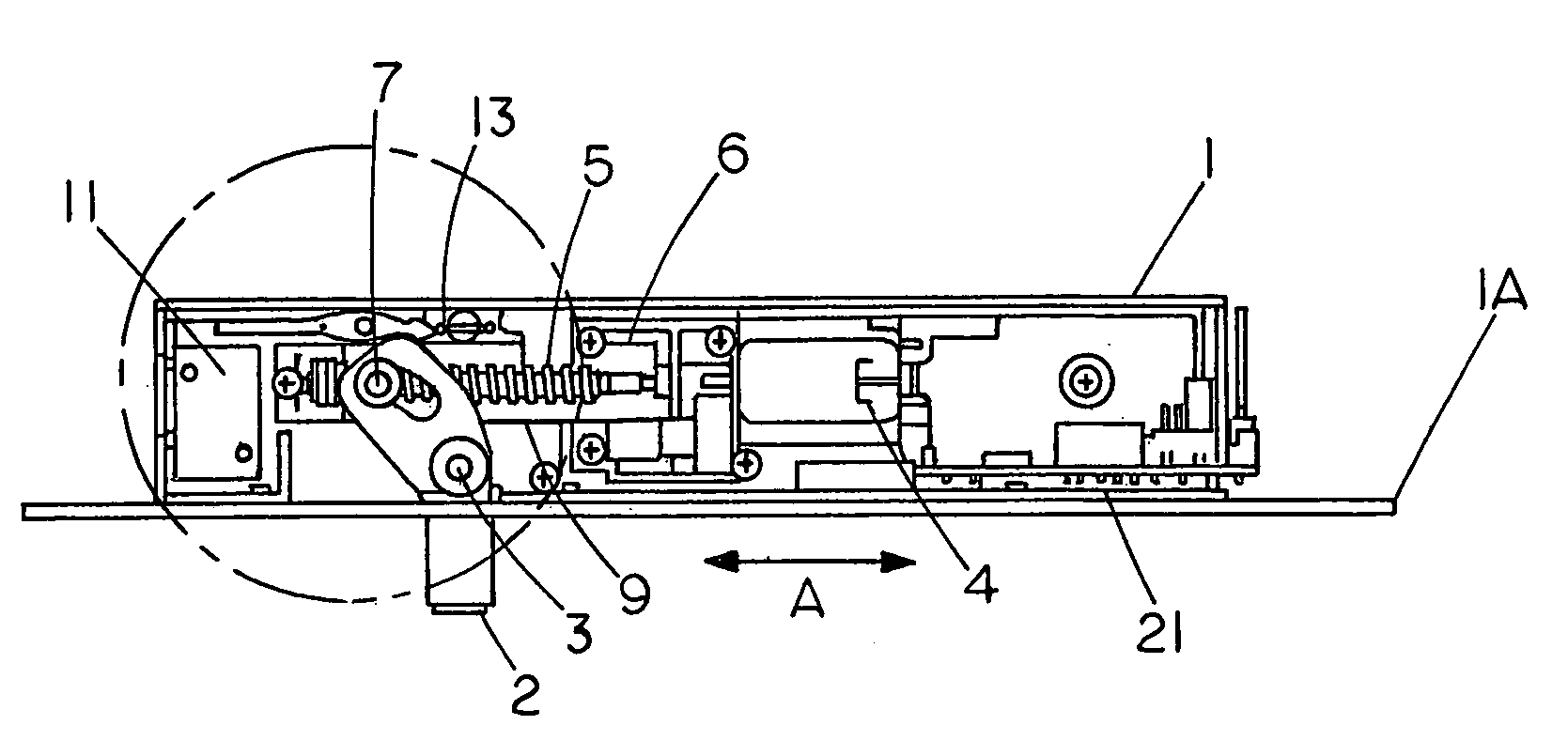
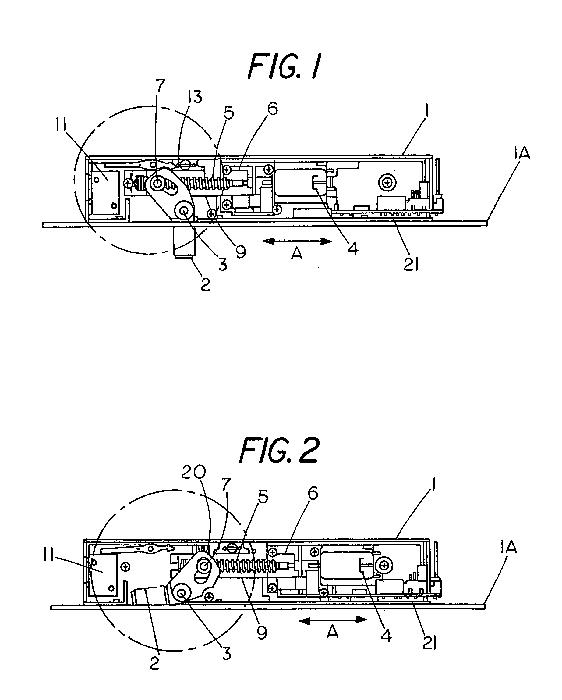
[0015]Referring first to FIG. 1 there is shown an electric lock comprising a housing 1 which is adapted for mounting into a doorway frame with face plate 1A facing outward. The housing has a bolt 2 pivoted about a pin 3 so that it can move between the locking configuration shown in FIG. 1 where it extends out from the frame and an unlocked configuration where it is substantially within the housing. The mechanical drive assembly for the bolt comprises an electric motor 4 which turns a screw shaft 5 through reduction gears 6. Mounted on the screw shaft 5 is a roller nut 7 which moves along the length of this shaft as said shaft is rotated by the motor. The roller nut 7 in turn engages a closed cam surface 8 formed as part of the bolt 2. When the mechanical drive assembly is in the normal operative position shown in FIG. 1 the roller nut, in accordance with the direction of motor rotation, moves either to the left end of the screw shaft 5 as shown in FIG. 1 or to the right end (not sho...


PUM


Abstract

There is an electric motor driven drop bolt having a housing which in use is mounted into a doorway frame and has the bolt pivotal therein by a mechanical drive set in a cage disposed at an operative position. The bolt is pivotal between a locking configuration where the bolt extends outward of the housing to engage in an aperture associated with a door within the frame and an unlocked configuration where the bolt is withdrawn to clear the aperture. The mechanical drive includes a screw shaft rotatable by the electric motor to move a roller nut along the length of the shaft whilst engaging a cam surface on the bolt. To obtain fail safe operation of the drop bolt the cage is slidable in the housing from the operative position to a disengaged position so that the bolt is movable from the locking configuration to the unlocked configuration without operation of the mechanical drive.

Description

FIELD OF THE INVENTION[0001]This invention relates to security locks. More particularly, although not exclusively, it discloses an improved electric motor driven drop bolt comprising user selectable power-to-open or power-to-lock conversion.BACKGROUND OF THE INVENTION[0002]The purpose of a drop bolt is to provide a concealed lock for a door or a movable barrier. In prior art devices a solenoid moves a bolt axially out from the doorway frame and into a strike plate set in the edge of the door. The strike plate has an aperture dimensioned to axially receive the bolt so that once it is in place the door is effectively locked. Such devices are generally used where security is desired as well as concealment of the installation when the door is locked.[0003]There are however a number of problems with the devices currently in use. If there is any misalignment of the door in the frame the bolt will hit the strike plate rather than seat in the hole. While with some systems the bolt will puls...

Claims


Application Information

Patent Timeline
IPC IPC(8): E05C3/06E05B47/02E05B15/02E05B17/00E05B47/00E05B47/06E05B63/00
CPCE05B47/0012E05B63/0013E05B47/0607E05B15/0205E05B17/0025E05B47/0002E05B2047/0076E05B63/0073E05B2047/0023E05B2047/0068E05B47/023Y10T292/1079Y10T292/1021Y10T292/1082B42D3/18B42D15/0053G09F23/10B42F5/00B42P2241/10
Inventor LUKER, GRAHAM JAMES
Owner ASSA ABLOY AUSTRALIA PTY LTD
Why Eureka
Try Eureka