Utility machinery and associated reversible feeder mechanisms

a technology of feeder mechanism and utility machinery, which is applied in the direction of agriculture, agriculture tools and machines, gearing, etc., can solve problems such as harvest delay, and achieve the effect of improving utility machinery

Active Publication Date: 2006-05-30
BLUE LEAF I P INC +1
View PDF17 Cites 12 Cited by
  • Summary
  • Abstract
  • Description
  • Claims
  • Application Information

AI Technical Summary

Problems solved by technology

Such a situation might cause one or both of the gathering elements to stall partially or fully, which can mean a delay in harvesting while the jam is cleared.

Method used


Image

  • Utility machinery and associated reversible feeder mechanisms
  • Utility machinery and associated reversible feeder mechanisms
  • Utility machinery and associated reversible feeder mechanisms

Examples


Embodiment Construction

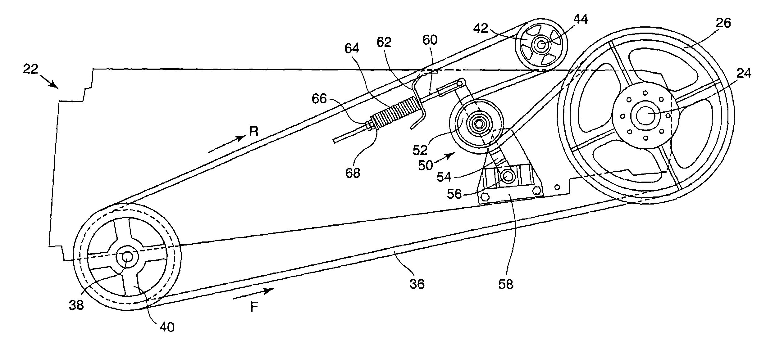
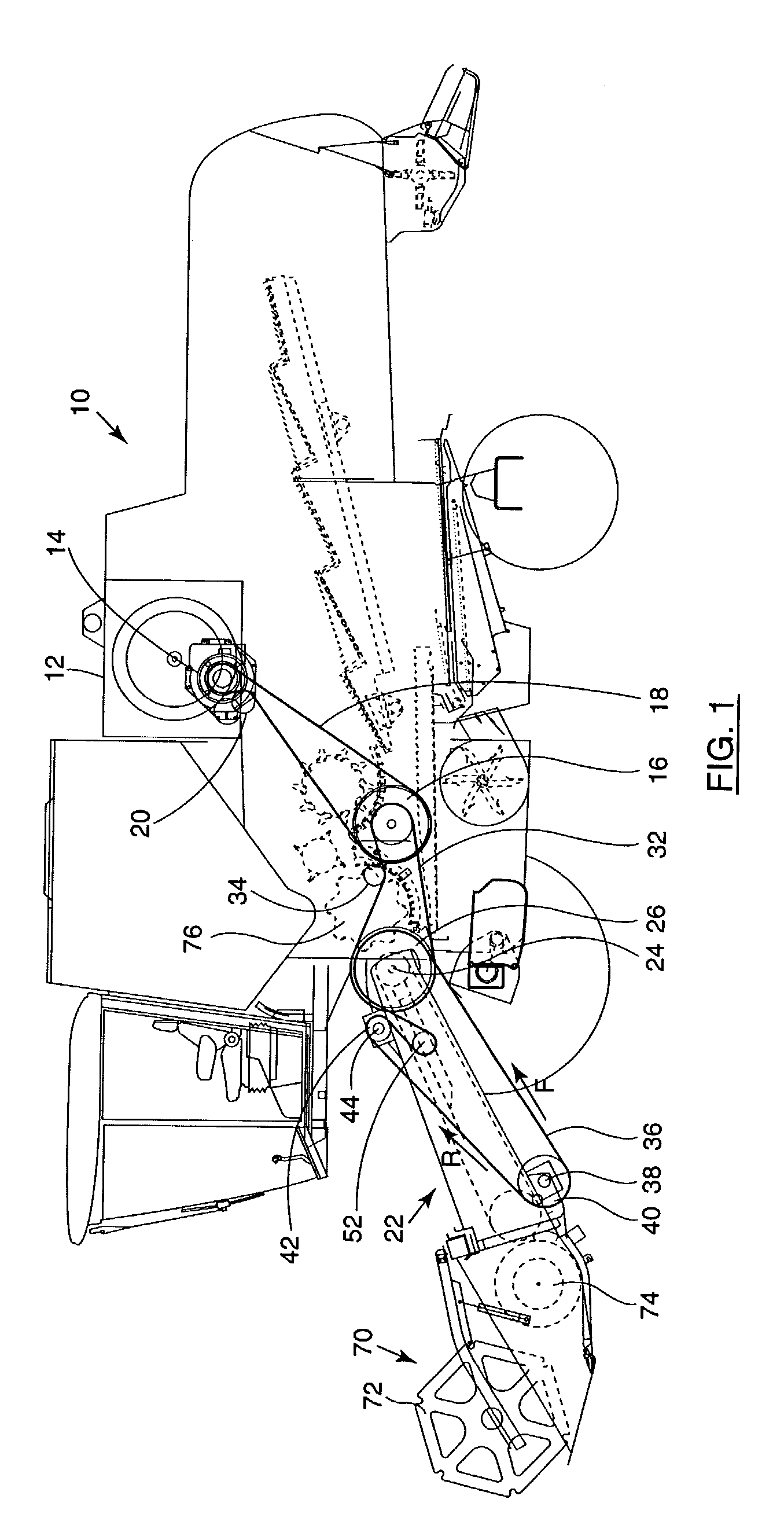
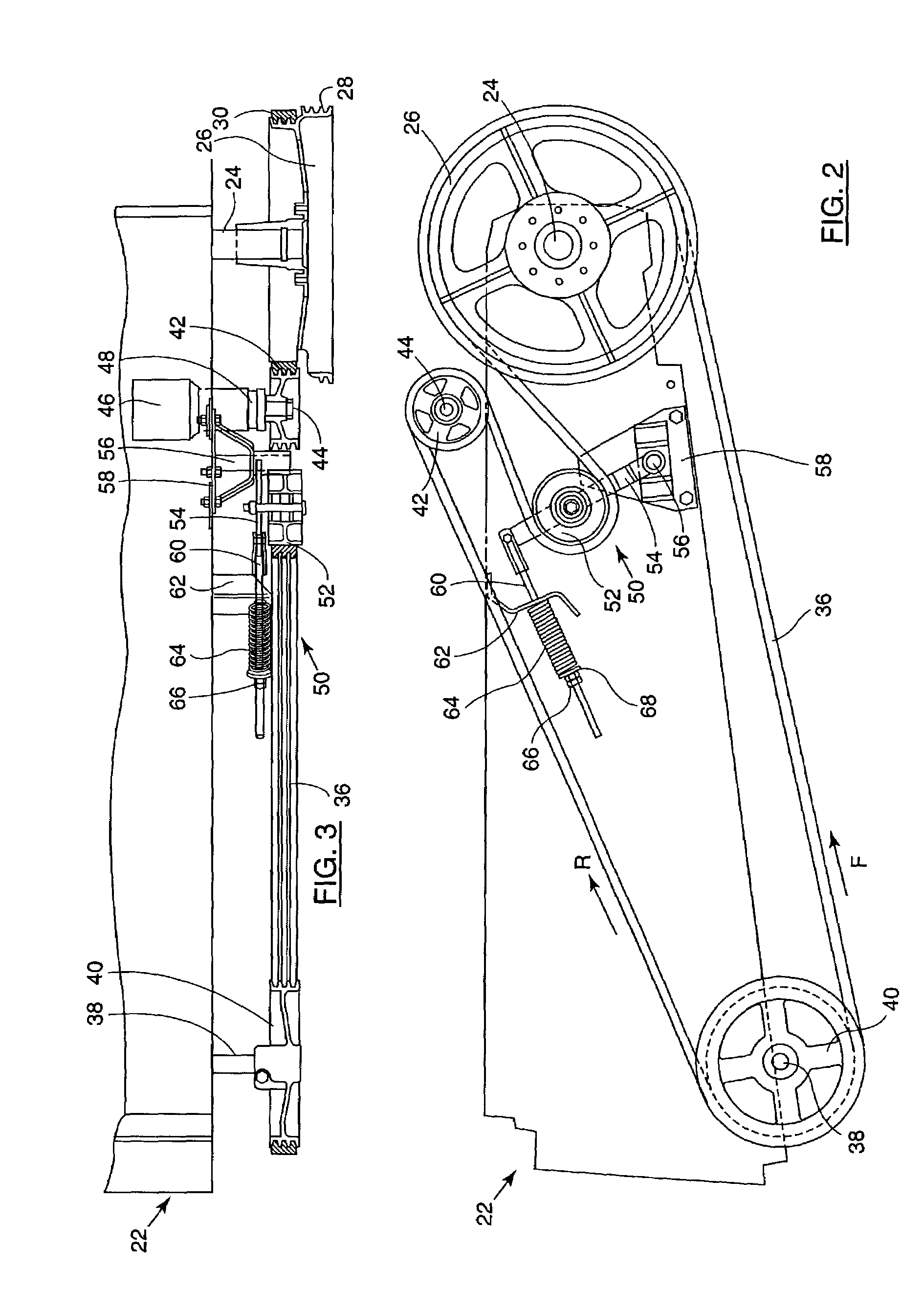
[0032]The present invention will now be described with reference to certain embodiments and with reference to the above mentioned drawings. Such description is by way of example only and the invention is not limited thereto. The drawings are schematic and the terms “front”, “rear”, “forward”, “rearward”, “right and “left” where used are determined with respect to the normal direction of movement of the machine in use. For convenience, the specific but non-limiting examples discussed herein will concentrate on agricultural machinery and in particular self-propelled combine harvesters, although it will be appreciated that similar arrangements may also be provided in other forms of agricultural crop processing machinery such as forage harvesters. Further utility machinery may comprise earth moving, processing or construction equipment. It will also be noted that the utility machinery need not be self propelled and that embodiments exist which are stationary or may be in trailer form, i...


PUM


Abstract

A drive mechanism for utility machinery is disclosed. The mechanism includes a driver wheel and a driven wheel that are coupled by means of an endless flexible band trained around outer rims of the driver and driven wheels. The driver wheel is adapted to transmit drive to the driven wheel in a forward direction F along a loaded side of the band. The mechanism further comprises an idler wheel that runs on an outer side of the band and applies an inwardly directed tensioning force to the band on a run of the band that is unloaded when forward drive is being transmitted. A reverse driver is positioned between the idler wheel and the driven wheel on an inner portion of the side of the band that is unloaded during forward drive. The reverse driver is adapted to selectively provide a reverse drive to the band.

Description

FIELD OF THE INVENTION[0001]The present invention relates to utility machinery and associated feeder mechanisms and in particular, but not exclusively, to arrangements adapted for reversing the operation of such feeder mechanisms.BACKGROUND TO THE INVENTION[0002]It is known to provide utility machinery with a feeder mechanism fed with material gathered by gathering elements. The gathering elements may be configured to gather the material from an operating area somewhat wider than the machine and to move the gathered material to the feeder mechanism. They may form a two stage gathering process, which initially involves collecting in the material across the width of a window of operation and moving some material inwards towards an intake mouth or conveyor of the feeder mechanism, e.g. material collected in portions of the operating area that lie outboard of that intake mouth / conveyor. The feeder mechanism then conveys the gathered material into the machine for processing and / or redist...

Claims


Application Information

Patent Timeline
Patent Type & Authority Patents(United States)
IPC IPC(8): F16H7/02A01D69/00
CPCA01D69/00A01D41/142
Inventor JONCKHEERE, MARC R. M.BOECK, OLDEMAR
Owner BLUE LEAF I P INC
Why Eureka
Try Eureka