
Apparatus for supplying raw material

a technology for supplying raw materials and apparatuses, applied in the direction of polycrystalline material growth, crystal growth process, protective fluid, etc., can solve problems such as difficulty in handling, and achieve the effect of effective absorption of falling energy of raw materials and scattering range of charged raw materials

Active Publication Date: 2006-05-30
SUMITOMO MITSUBISHI SILICON CORP
View PDF4 Cites 2 Cited by
  • Summary
  • Abstract
  • Description
  • Claims
  • Application Information

AI Technical Summary

Benefits of technology

"The present invention provides an apparatus for supplying a raw material for single crystal growth using a CZ method, which prevents melt splashing and wear loss of the vertical charging tube. The apparatus includes a raw material accumulating section that allows a predetermined amount of raw material to accumulate in the vertical charging tube and prevents excess raw material from falling down. The accumulated raw material acts as a cushion and protects the vertical charging tube from damage. The use of a polycrystalline raw material with a particle size of -30 mm or less helps to avoid splashing caused by oxides on the surface. The apparatus can be connected to a top chamber of a CZ pulling furnace, making it convenient for different CZ pulling apparatuses. The vertical charging tube has a guide section to restrict the scattering range of the charged raw material. Overall, the invention provides a safer and more efficient method for supplying raw material for single crystal growth."

Problems solved by technology

That is, if particle diameters exceeds 30 mm, an opening diameter of a charging tube or the like is required to be larger in order to charge the raw material without causing clogging, which necessitates scaling-up of the facility, leading in turn to difficulty in handling.

Method used


Image

  • Apparatus for supplying raw material
  • Apparatus for supplying raw material
  • Apparatus for supplying raw material

Examples


Embodiment Construction

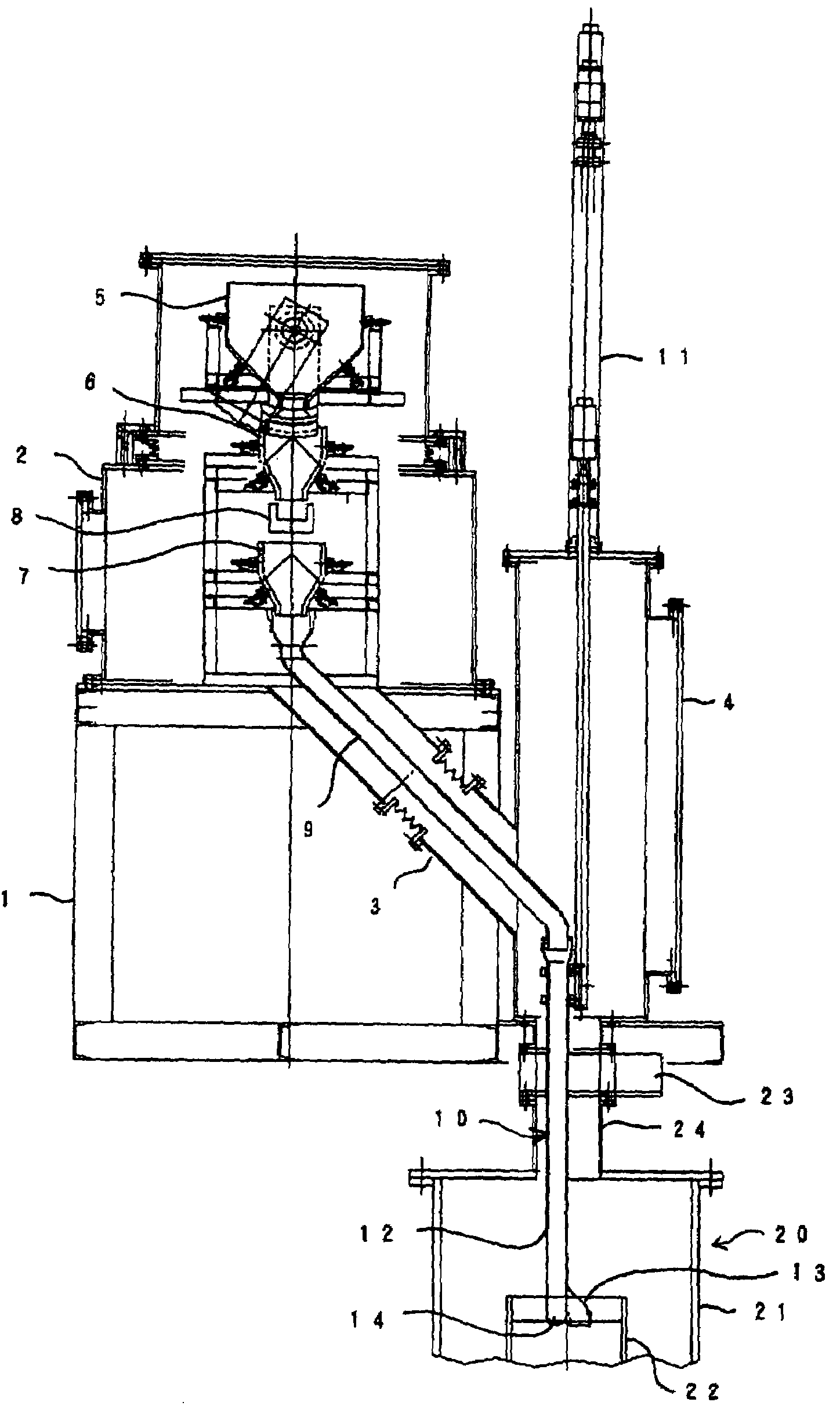
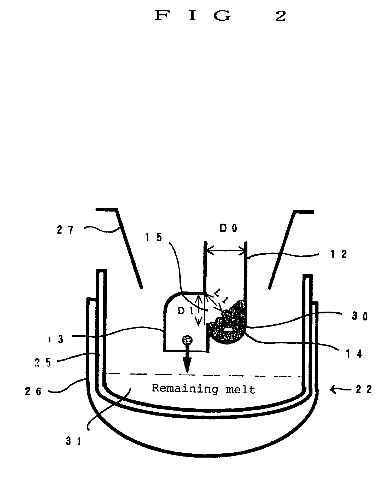
[0023]Description will be given of an embodiment of the present invention below based on the accompanying drawings. FIG. 1 is a view of the construction of a raw material supply apparatus showing an embodiment of the present invention and FIG. 2 is a longitudinal sectional view of a main section of the raw material supply apparatus.

[0024]A raw material supply apparatus of this embodiment is of a transportable type moving in both ways between a position above a CZ pulling furnace 20 and a retreat place to a side thereof and connected to a top chamber 24 on a main chamber 21 instead of a pull chamber when in recharge and thereby, a polycrystalline raw material, especially a lump raw material having a particle diameter of 30 mm or less, is automatically charged into a crucible 22 in the main chamber 21.

[0025]The transportable raw material supply apparatus has a first chamber 2 mounted on a moving frame 1 and a second chamber 4. The second chamber 4 communicates with a side of the first...


PUM

PropertyMeasurementUnit
particle diameteraaaaaaaaaa
particle diametersaaaaaaaaaa

Abstract

In single crystal growth by means of a CZ method, a granular / lump polycrystalline raw material is additionally supplied into a raw material melt in a crucible through a vertical charging tube. A raw material accumulating section is provided at a site part way downward in the vertical charging tube working in such a way that a predetermined amount of the polycrystalline raw material is accumulated in the raw material accumulating section and the polycrystalline raw material in excess of the predetermined amount falls down. The polycrystalline raw material falling down in the vertical charging tube strikes against the accumulated raw material in the raw material accumulating section, thereby absorbing a shock of the falling raw material. The accumulated raw material works simultaneously as a protective member, thereby preventing breakage of the tube accompanying absorption of the shock from occurring. It is therefore possible to prevent melt splashing that is problematical when a lump raw material for recharge is charged using a vertical charging tube.

Description

BACKGROUND OF THE INVENTION[0001]1. Field of the Invention[0002]The present invention relates to an apparatus for supplying raw material used in single crystal growth by means of a CZ method, and more particularly, to an apparatus for supplying raw material used in charging granular / lump polycrystalline raw material into a crucible.[0003]2. Description of the Background Art[0004]A silicon single crystal, which serves as a material of a semiconductor device, is exclusively used by means of a CZ method for the industrial purpose. In single crystal growth by means of a CZ method, solid poly-silicon initially charged in a crucible is molten by heating with a heater. When a raw material melt is formed in such a way in the crucible, a seed crystal is dipped into the raw material melt in the crucible and starting in this state, the seed is raised while rotating the seed and the crucible, thereby growing a silicon single crystal in the shape of a cylinder at and below the lower end of the s...

Claims


Application Information

Patent Timeline
Patent Type & Authority Patents(United States)
IPC IPC(8): C30B25/12C30B25/14C30B15/02C30B29/06
CPCC30B15/02Y10T117/1056Y10T117/1032Y10T117/1052Y10T117/10
Inventor WATANABE, HIDEKIASANO, HIROSHIONISHI, MASAKAZU
Owner SUMITOMO MITSUBISHI SILICON CORP
Learn More