Sentry robot system

a robot system and robot technology, applied in the field of robot systems, can solve the problems of limited economic benefits of non-autonomous robots, inability to autonomously navigate, and the majority of mobile robots are non-autonomous

Inactive Publication Date: 2006-05-30
ROYAL APPLIANCE MFG
View PDF23 Cites 279 Cited by
  • Summary
  • Abstract
  • Description
  • Claims
  • Application Information

AI Technical Summary

Problems solved by technology

Most mobile robots are non-autonomous; that is, they are unable to autonomously navigate.
The economic benefits provided by non-autonomous robots are limited by the inflexible behavior of the robots and their extensive installation costs.
If the environment is modified significantly, however, such as by moving a large item of furniture, conventional non-autonomous robots do not properly react.
Given this limitation, non-autonomous robots are usually deployed only on stable and high value routes.
Though some non-autonomous robots rely on random motion to perform their tasks, such as pool cleaning robots, only a limited number of applications are amenable to this approach.
Autonomous robots that rely on 2D mapping and localization are often not able to navigate with adequate reliability due to the relative simplicity of the map.
Often, the robots become lost, stuck or fall.
3D maps typically have millions of cells, making straightforward operations such as landmark extraction, localization and planning computationally intensive.
The resulting computational delays limit the speed of robot movement and task performance.
With one robot attempting to localize while performing tasks leads to unacceptable delays.

Method used


Image

  • Sentry robot system
  • Sentry robot system
  • Sentry robot system

Examples


Embodiment Construction

[0033]While the invention is described in conjunction with the accompanying drawings, the drawings are for purposes of illustrating exemplary embodiments of the invention and are not to be construed as limiting the invention to such embodiments. It is understood that the invention may take form in various components and arrangements of components and in various steps and arrangements of steps beyond those provided in the drawings and associated description. Within the drawings, like reference numerals denote like elements.

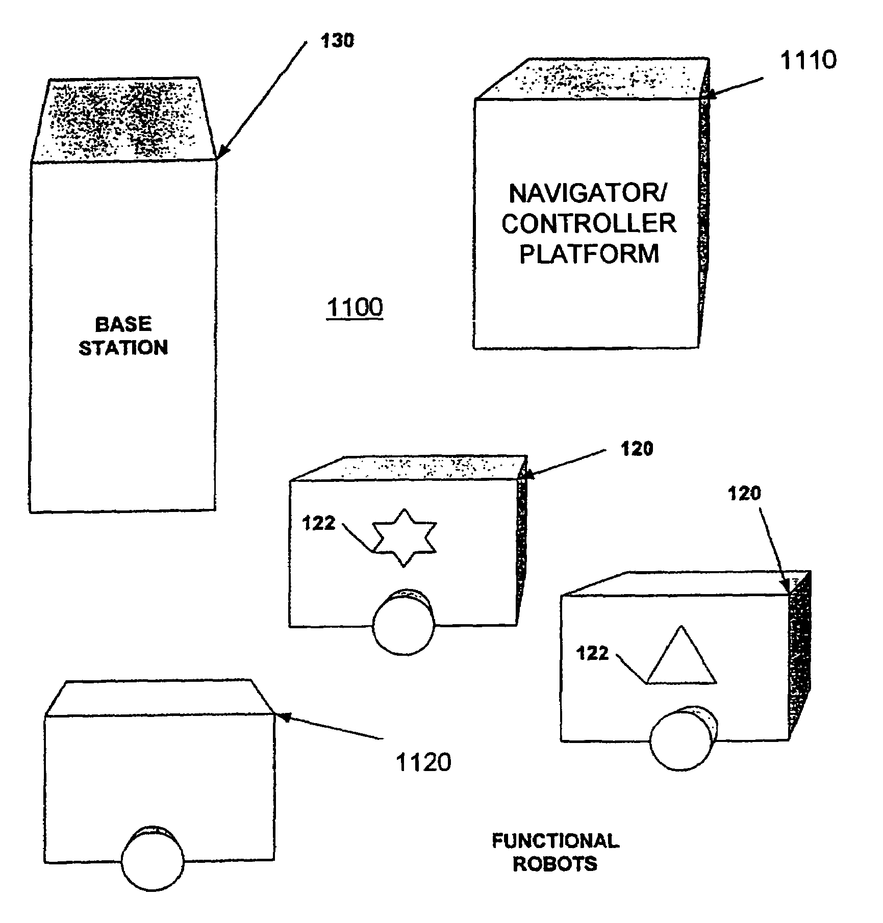
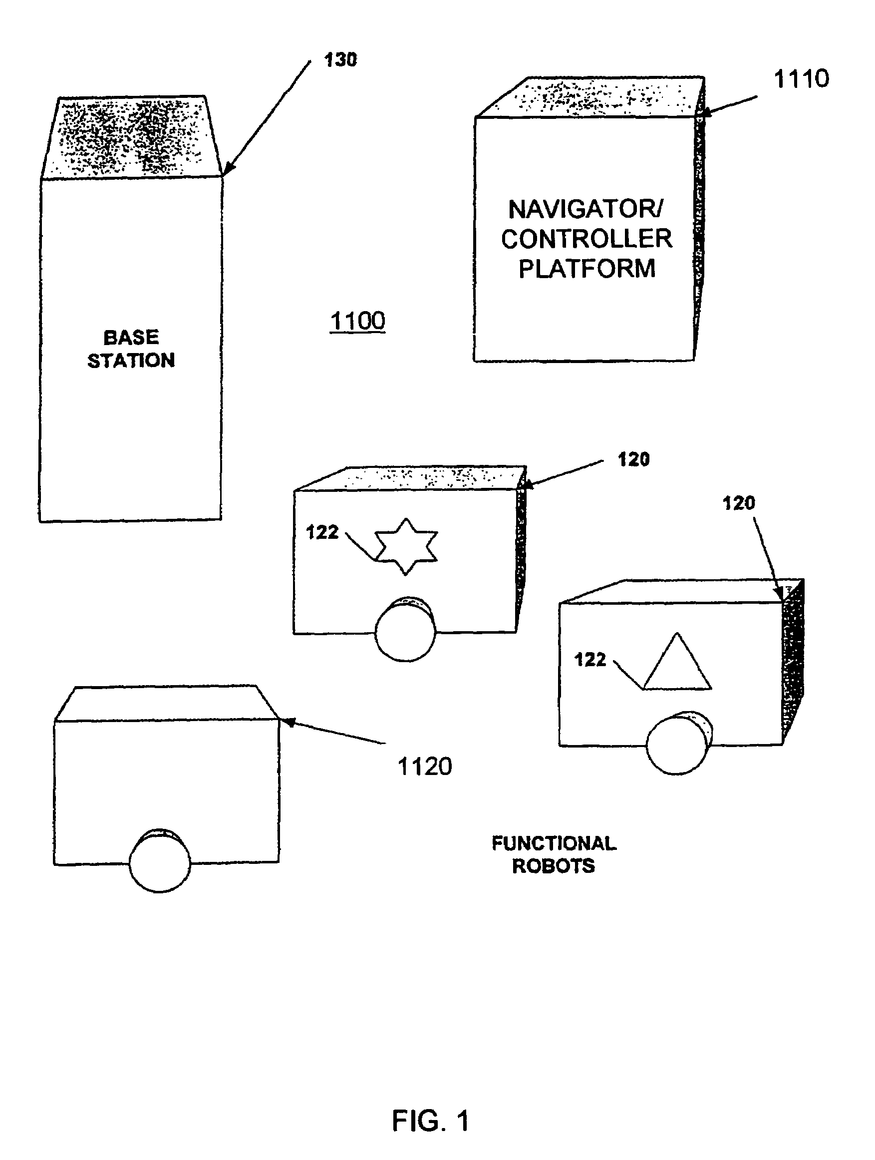
[0034]FIG. 1 is a block diagram of a robot system 1100 in one embodiment of the invention. System 1100 includes one or more navigator / controller platforms 1110, one or more functional robots 120, 1120, and (optionally) one or more a base stations 130. The functional robots 120, 1120 may include functional robots with environmental sensors 1120 and functional robots without environmental sensors 120. The functional robots with environmental sensors 1120 may be consi...


PUM


Abstract

A sentry robot system and method for operating the system is provided. In one embodiment, the robot system includes at least one functional robot with one or more environmental sensors and at least one navigator / controller platform. In another embodiment, the robot system includes one or more functional robots, one or more environmental sensors associated with at least one of the functional robots, and one or more navigator / controller platforms. The navigator / controller platform in this embodiment includes a receiver, a controller, a memory, and a transmitter. In one embodiment, the method includes creating an image map of the environment from environment data, periodically moving the functional robot to predetermined locations, collecting new environment data using the optical image sensor at each predetermined location, and comparing the new environment data to corresponding locations in the image map, and periodically determining if intervention is required due to changed conditions within the environment.

Description

[0001]This application claims the benefit of U.S. Provisional Application Ser. No. 60 / 408,693, filed on Sep. 6, 2002, the disclosure of which is incorporated herein by reference.BACKGROUND OF INVENTION[0002]The invention relates to robot systems. It finds particular application in conjunction with a system and method for allocating mapping, localization, planning, control and task performance functions in a sentry robot system and will be described with particular reference thereto. However, it is to be appreciated that the invention is also amenable to other applications.[0003]Mobile robots have been designed, developed and deployed to handle a variety of tasks such as cleaning and security. Most mobile robots are non-autonomous; that is, they are unable to autonomously navigate. The economic benefits provided by non-autonomous robots are limited by the inflexible behavior of the robots and their extensive installation costs. Skilled technicians often must be hired and paid to prep...

Claims


Application Information

Patent Timeline
Patent Type & Authority Patents(United States)
IPC IPC(8): G06F19/00G05D1/02
CPCG05D1/0251G05D1/0274G05D1/0282G05D1/0285G05D1/0287G05D1/0225G05D2201/0211G05D2201/0203G05D2201/0207G05D2201/0208G05D2201/0209
Inventor MCKEE, ROBERT N.HOLCOMB, JIM
Owner ROYAL APPLIANCE MFG
Why Eureka
Try Eureka