
Windscreen wiper device

Inactive Publication Date: 2006-06-06
TRICO BELGIUM SA
View PDF13 Cites 20 Cited by
  • Summary
  • Abstract
  • Description
  • Claims
  • Application Information

AI Technical Summary

Benefits of technology

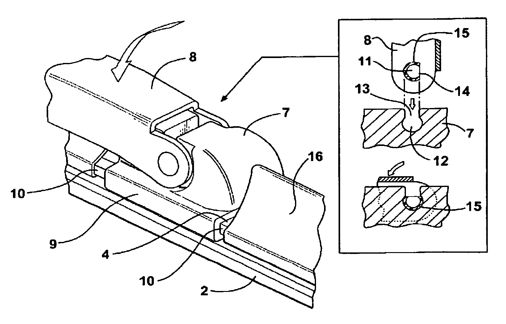
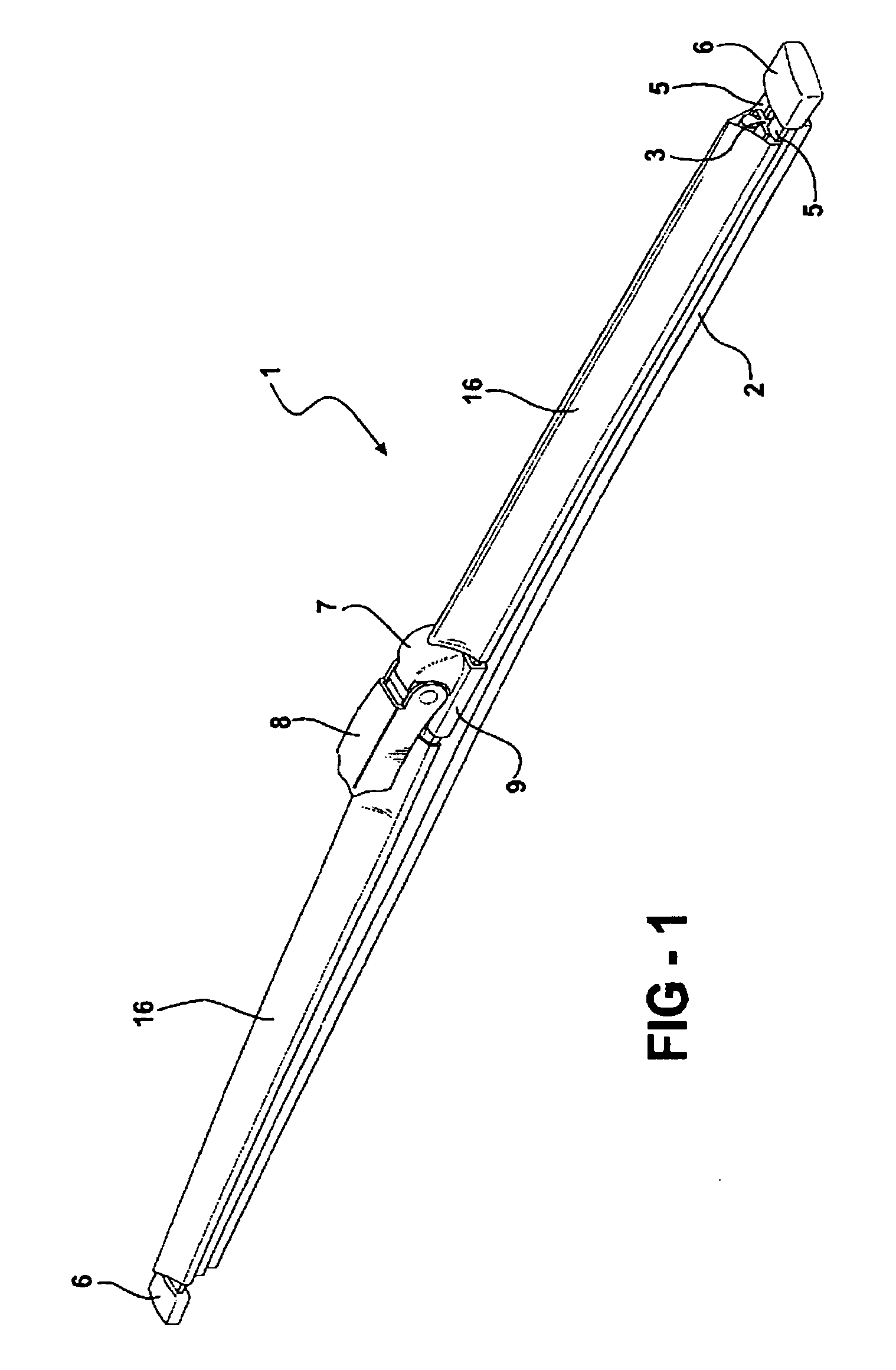
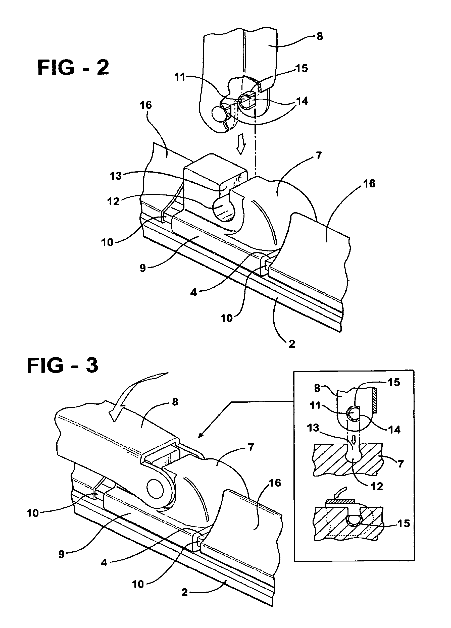
[0009]In another preferred embodiment of a windscreen wiper device according to the invention, the shaft is dimensioned such that it can be passed through an insertion opening of the recess from an at least substantially perpendicular position of the oscillating arm with respect to the wiper blade, and be locked in position in said recess from an at least substantially parallel position of the oscillating wiper arm with respect to the wiper blade. This makes it possible to move, in particular pivot, the oscillating wiper arm from a mounting position (that is, a (vertical) position perpendicularly to the wiper blade or the plane of a windscreen to be wiped) to an operative position (that is, a (horizontal) position parallel to the wiper blade or the plane of a windscreen to be wiped). In the mounting position, the shaft can be freely inserted into the insertion opening of the recess and subsequently be mounted in said recess, whilst in the operative position the shaft is locked in position in said recess, so that it cannot move out of said recess via the insertion opening.
[0010]In another preferred embodiment of a windscreen wiper according to the invention, the shaft is formed by two protrusions each extending inwardly on a leg of the U-shaped cross-section. Preferably said protrusions are at least substantially cylindrical and form at least substantially cylindrical bearing surfaces. The two protrusions that function as bearing surfaces are spaced far apart, so that the forces that are exerted on said bearing surfaces will be relatively low.

Problems solved by technology

One drawback of the prior art windscreen wiper device is the fact that in practice the forces (torques) that are exerted on the connection between the connecting device and the oscillating arm appear to be relatively high, as a result of which the reliability of said connection appears to diminish with the passage of time.

Method used


Image

  • Windscreen wiper device
  • Windscreen wiper device
  • Windscreen wiper device

Examples


Embodiment Construction

[0022]FIGS. 1, 2 and 3 show a preferred variant of a windscreen wiper device 1 according to the invention. Said windscreen wiper device is built up of an elastomeric wiper blade 2, in the longitudinal sides of which opposing longitudinal grooves 3 are formed, and of longitudinal strips 4 made of spring band steel, which are fitted in said longitudinal grooves 3. Said strips 4 form a flexible carrier element for the rubber wiper blade 2, as it were, which is thus biassed in a curved position (the curvature in operative position being that of a windscreen to be wiped). Neighbouring ends 5 of strips a are interconnected on either side of the windscreen wiper device 1 by means of connecting pieces 6 functioning as clamping members. In this embodiment, the connecting pieces 6 are separate constructional elements, which may be form-locked (“positive locking” or “having positive fit”) as well as force-locked to the ends 5 of strips 4. In another preferred variant, said connecting pieces 6 ...


PUM

PropertyMeasurementUnit
Forceaaaaaaaaaa
Electrical resistanceaaaaaaaaaa

Abstract

A windscreen wiper device comprising an elastic, elongated carrier element, as well as an elongated wiper blade of a flexible material, which windscreen wiper device comprises a connecting device for an oscillation wiper arm, wherein the oscillating arm is pivotally connected to the connecting device about a pivot axis near one end. The end of the oscillating wiper arm has an at least substantially U-shaped cross-section and the connecting device is at least partly positioned within the end of the oscillating arm. The end of the oscillating arm is provided, at the location of the pivot axis, with a shaft extending between the legs of the U-shaped cross-section. The shaft is pivotally engaged in the connecting device.

Description

BACKGROUND OF THE INVENTION[0001]1. Technical Field[0002]The invention relates to a windscreen wiper device comprising an elastic, elongated carrier element, as well as an elongated wiper blade of a flexible material, which can be placed in abutment with a windscreen to be wiped, which wiper blade includes opposing longitudinal grooves on its longitudinal sides, in which grooves spaced-apart longitudinal strips of the carrier element are disposed, wherein neighbouring ends of said longitudinal strips are interconnected by a respective connecting piece, which windscreen wiper device comprises a connecting device for an oscillating wiper arm, wherein said oscillating arm is pivotally connected to said connecting device about a pivot axis near one end.[0003]2. Related Art[0004]Such a windscreen wiper device is generally known. The prior art windscreen wiper device is in particular designed as a “yokeless” wiper device, wherein use is no longer made of several yokes pivotally connected ...

Claims


Application Information

Patent Timeline
IPC IPC(8): B60S1/40B60S1/38
CPCB60S1/3849B60S1/4038B60S1/4064Y10T29/49Y10T29/49826B60S1/4041B60S1/40
Inventor BOLAND, XAVIER
Owner TRICO BELGIUM SA
Learn More