
Electrostatically dissipative athletic shoe

Inactive Publication Date: 2006-06-06
ELSEY WAYNE
View PDF25 Cites 11 Cited by
  • Summary
  • Abstract
  • Description
  • Claims
  • Application Information

AI Technical Summary

Benefits of technology

[0014]It is a further object of the present invention to provide an electrostatically dissipative athletic shoe that provides for increased control of electrostatic dissipation.
[0015]It is still a further object of the present invention to provide an electrostatically dissipative athletic shoe that provides for decreased manufacturing cost.

Problems solved by technology

However, the material limits imposed by such processes have deprived them of achieving complete success.
Integrated electronic components have always been susceptible to damage from the electrostatic charges that normally build up on a workers'body as the worker moves about.
These charges can be as high as 20,000 volts and may be conducted into the components so as to arc across individual transistors inside, permanently damaging them.
This risk continues to increase as the spacing between current carrying paths on the integrated circuits become closer together, in order to increase the density of electronic components on the integrated circuit.
As the conductive extension is formed of the same material as the outsole, this has a disadvantage of increasing the relative amount of outsole material required to form the shoe, defeating to some extent the gains achieved by splitting the cup sole into an outsole and a midsole.
An additional disadvantage of the conductive integral extension is that it forms an additional structural member that impacts and alters the desired characteristics of the shoe.
Cheskin recognizes, however, that the materials of which a sockliner, insole, midsole and outsole are comprised are typically different and separate, so that creating an effective electrically conductive path between the bottom of the wearer's foot and the outsole is difficult.

Method used


Image

  • Electrostatically dissipative athletic shoe
  • Electrostatically dissipative athletic shoe

Examples


Embodiment Construction

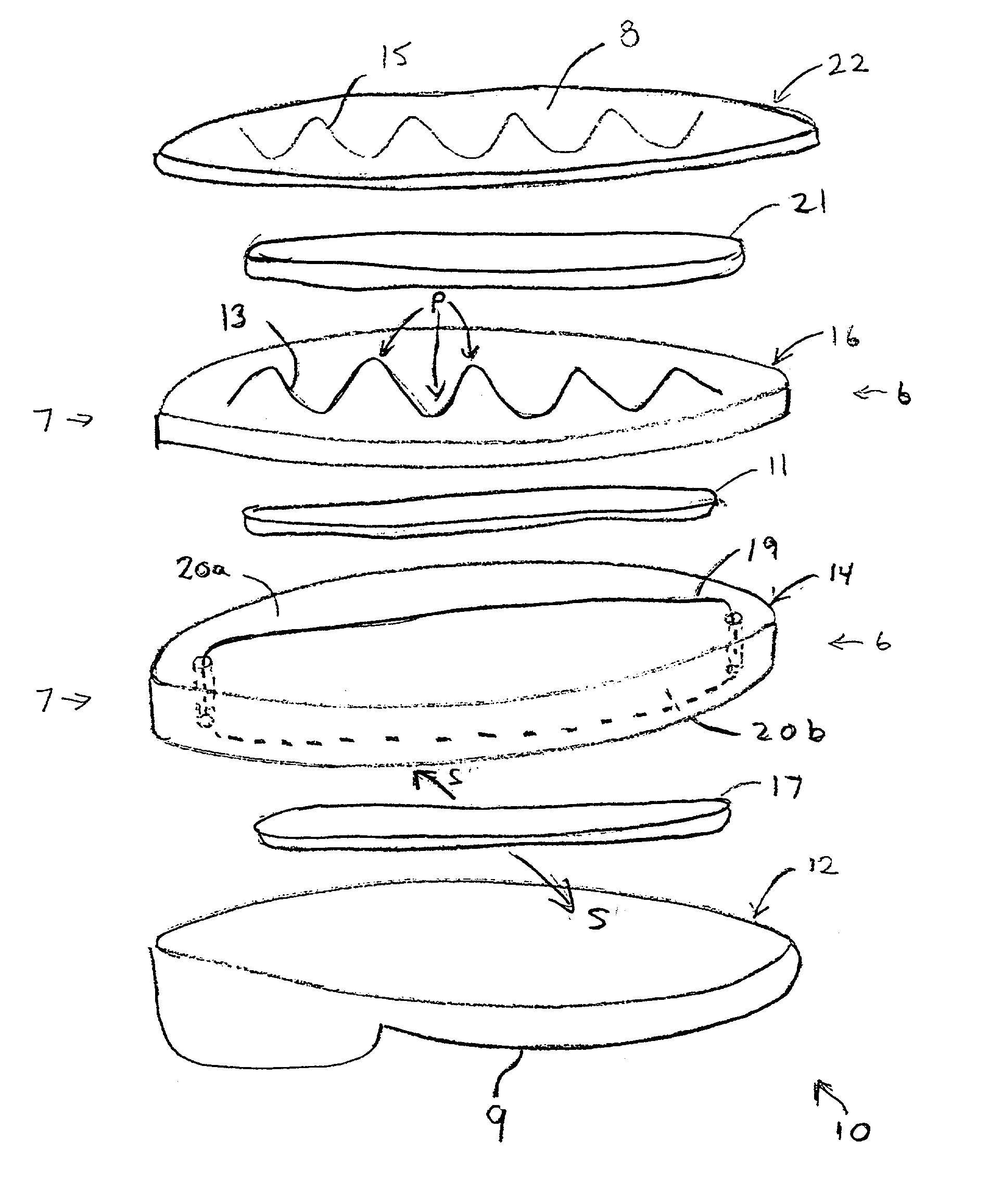
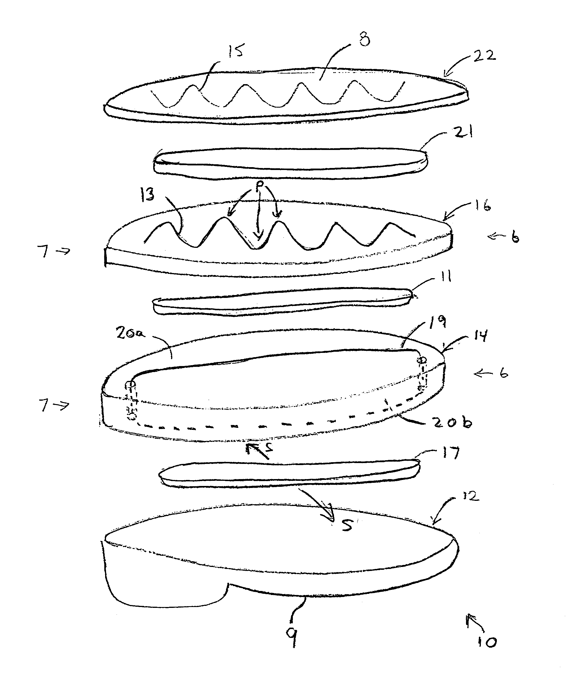
[0018]Referring to the FIGURE, an electrostatically dissipative athletic shoe 10 according to the present invention is shown. The shoe is formed of a number of stacked layers, and preferably provides for a “type 1” ESD rating; more particularly, the overall resistance between the top surface 8 of an uppermost layer and the bottom surface 9 of a bottommost layer of the shoe is preferably between about 2 and about 10 megohms. In a preferred embodiment of the invention, the shoe 10 has at least three such layers.

[0019]Particularly, the shoe 10 comprises an outsole layer 12 (hereinafter “outsole”), a midsole layer 14 (hereinafter “midsole”), and an insole layer 16 (hereinafter “insole”), the terms “outsole”, “midsole” and “insole” having meanings as they are ordinarily understood in the art of athletic shoe design.

[0020]The insole 16 is preferably formed of a fabric material, such as nylon, about 2.0 mm thick. The fabric construction of the insole 16, which incorporates woven or non-wov...


PUM


Abstract

An electrostatically dissipative athletic shoe. The shoe includes an outsole, a midsole, and an insole. The insole is preferably formed of a nylon fabric material. The insole is stitched with an electrically conductive thread in a zig-zag pattern, and electrically conductive glue is provided between the insole and the midsole and is disposed so as to make contact with the ESD thread. Preferably, the midsole includes at least two spaced-apart holes therethrough and an electrically continuous loop of ESD thread passes loosely through the holes and across opposite top and bottom surfaces of the midsole. Preferably, ESD glue is provided between the outsole and the midsole and is disposed so as to make contact with the loop. Preferably, the shoe includes a sockliner that is also stitched with an electrically conductive thread in a zig-zag pattern, and electrically conductive glue is provided between the sockliner and the insole and is disposed so as to make contact with the ESD thread of the sockliner and the ESD thread of the insole.

Description

FIELD OF THE INVENTION[0001]The present invention relates to an electrostatically dissipative athletic shoe, which combines the comfort and wear characteristics of an athletic shoe with the characteristic of type 1 or 2 electrostatic dissipation (hereinafter “ESD”).BACKGROUND OF THE INVENTION[0002]Athletic shoes are known to be more comfortable and lighter in weight than traditional footwear formed of a single “cup” sole. This is because the cup sole has had to provide, by itself, a number of different properties, including hardness or anti-wearing capability, shock absorption and spring, and optimizing these properties typically requires trade-offs.[0003]The athletic shoe provides a two-part sole employing an outsole and a separate midsole overlying the outsole. By essentially splitting the cup sole into two parts, it is possible to tailor each part more particularly for its function and achieve increases in performance and comfort along with decreases in weight. For example, the o...

Claims


Application Information

Patent Timeline
IPC IPC(8): A43B13/38A43B5/00A43B7/36A43B13/12
CPCA43B5/00A43B13/12A43B7/36
Inventor ELSEY, WAYNE
Owner ELSEY WAYNE
Learn More