
Electrically-driven steering lock device

a technology of steering lock and electric drive, which is applied in the direction of mechanical control devices, anti-theft devices, instruments, etc., can solve the problems of impeded steering shaft movement, impeded steering shaft locking of the vehicle in the midst of traveling, and inability to rotate, so as to improve safety while the vehicle is traveling, impede the movement of the lock stopper, and improve the anti-theft quality. effect of vehicle parked

Inactive Publication Date: 2006-06-06
KK TOKAI RIKA DENKI SEISAKUSHO
View PDF28 Cites 27 Cited by
  • Summary
  • Abstract
  • Description
  • Claims
  • Application Information

AI Technical Summary

Benefits of technology

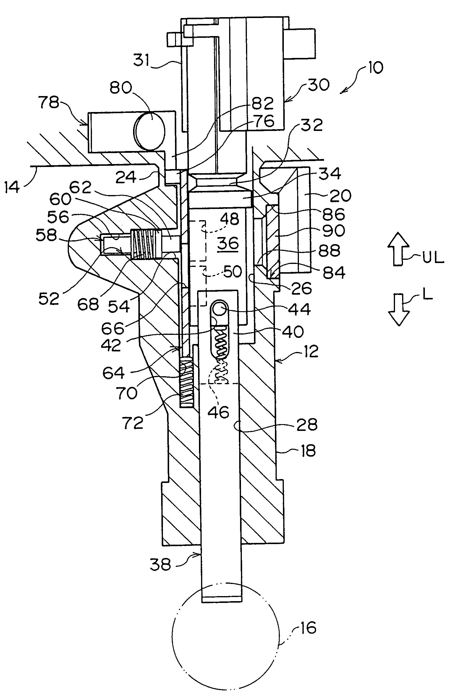
The present invention provides an electrically-driven steering lock device that can reliably maintain the locked state of the steering shaft even if the lock body is broken while the vehicle is parked. The device includes a lock body, a lock plate, an urging means, a lock pin, and a fit-in concave portion. The lock plate is movable between the guide portion and the lock body and can be divided if the impact of a predetermined value or more is applied to the lock body. The lock pin is inserted through the lock plate and fits into the fit-in concave portion of the lock stopper to prevent the locking of the steering shaft from being canceled. The lock plate and the urging means are provided at the interior of the guide portion and are not exposed, making it difficult to learn the mechanism and position of the lock pin. The technical effect of the invention is to improve the security and antitheft quality of the electrically-driven steering lock device.

Problems solved by technology

In an electrically-driven steering lock device having the above-described structure, the distal end portion of the lock bar projects toward the steering shaft and locks the steering shaft such that rotation thereof is not possible.
Moreover, the steering lock device disclosed in JP-A No. 7-9944, is provided with an impeding means such that, accompanying the breaking of the guide portion of the lock body, the engagement of the lock stopper and the lock bar is cancelled, the lock bar becomes able to move, and locking of the steering shaft of the vehicle which is in the midst of traveling is impeded.
Therefore, there is the concern that the engagement of the engaging member with the lock bar can be impeded by fixing the engaging member in advance before breaking the lock body.
However, in the above-described steering lock device disclosed in JP-A No. 2000-225922, because the restricting member is cleared away together with the main body portion as the main body portion and the guide portion are divided, a gap forms between the guide portion and the cam shaft.

Method used


Image

  • Electrically-driven steering lock device
  • Electrically-driven steering lock device
  • Electrically-driven steering lock device

Examples


Embodiment Construction

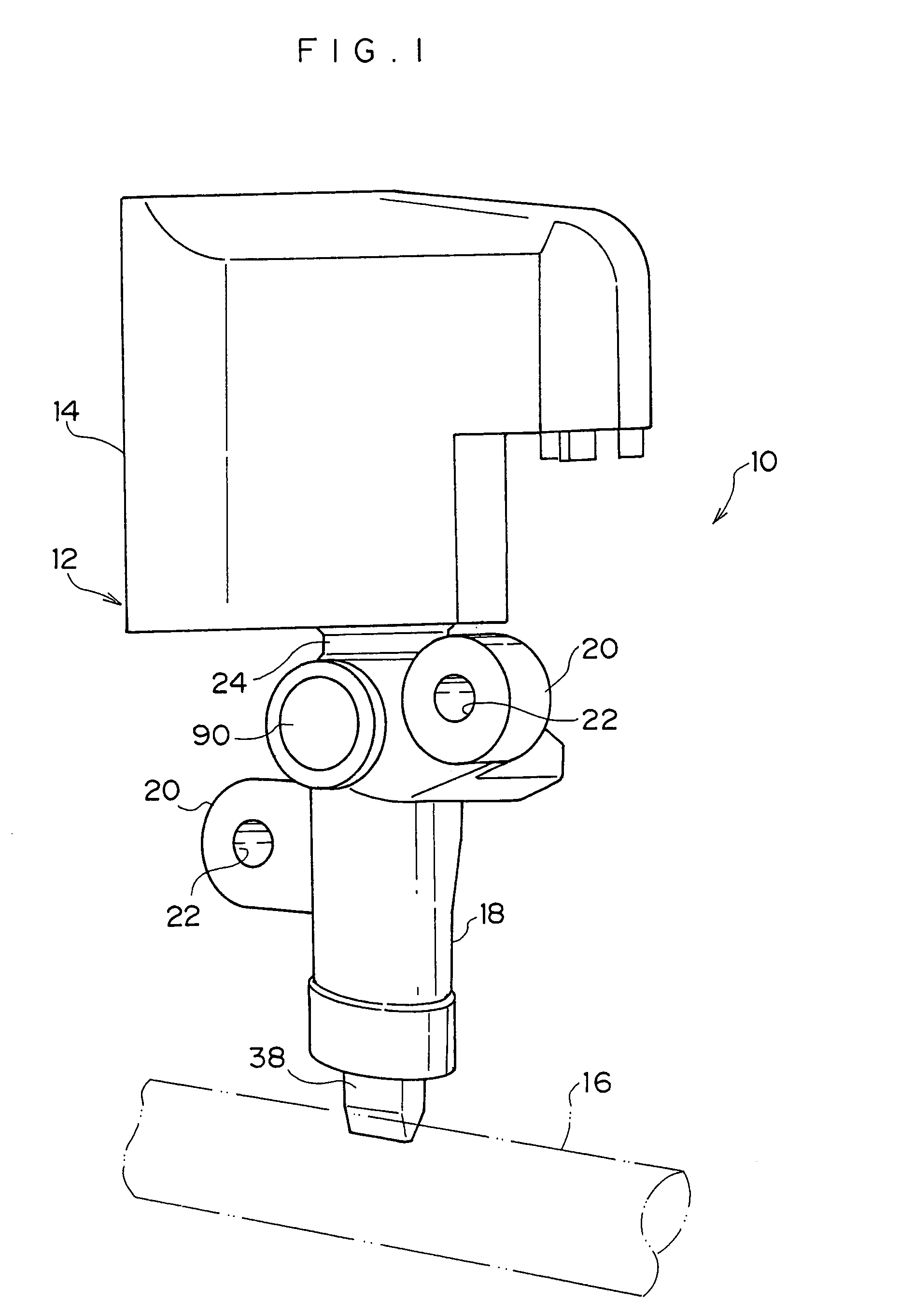
[0053]The structure of an electrically-driven steering lock device 10 relating to an embodiment of the present invention is shown in a perspective view in FIG. 1.

[0054]The electrically-driven steering lock device 10 has a lock body 12 mounted to the steering post (not illustrated) of a vehicle. The lock body 12 is formed of a metal, and has a box-shaped main body portion 14 and a tubular guide portion 18 which projects from the main body portion 14 toward a steering shaft 16. The main body portion 14 and the guide portion 18 are integral.

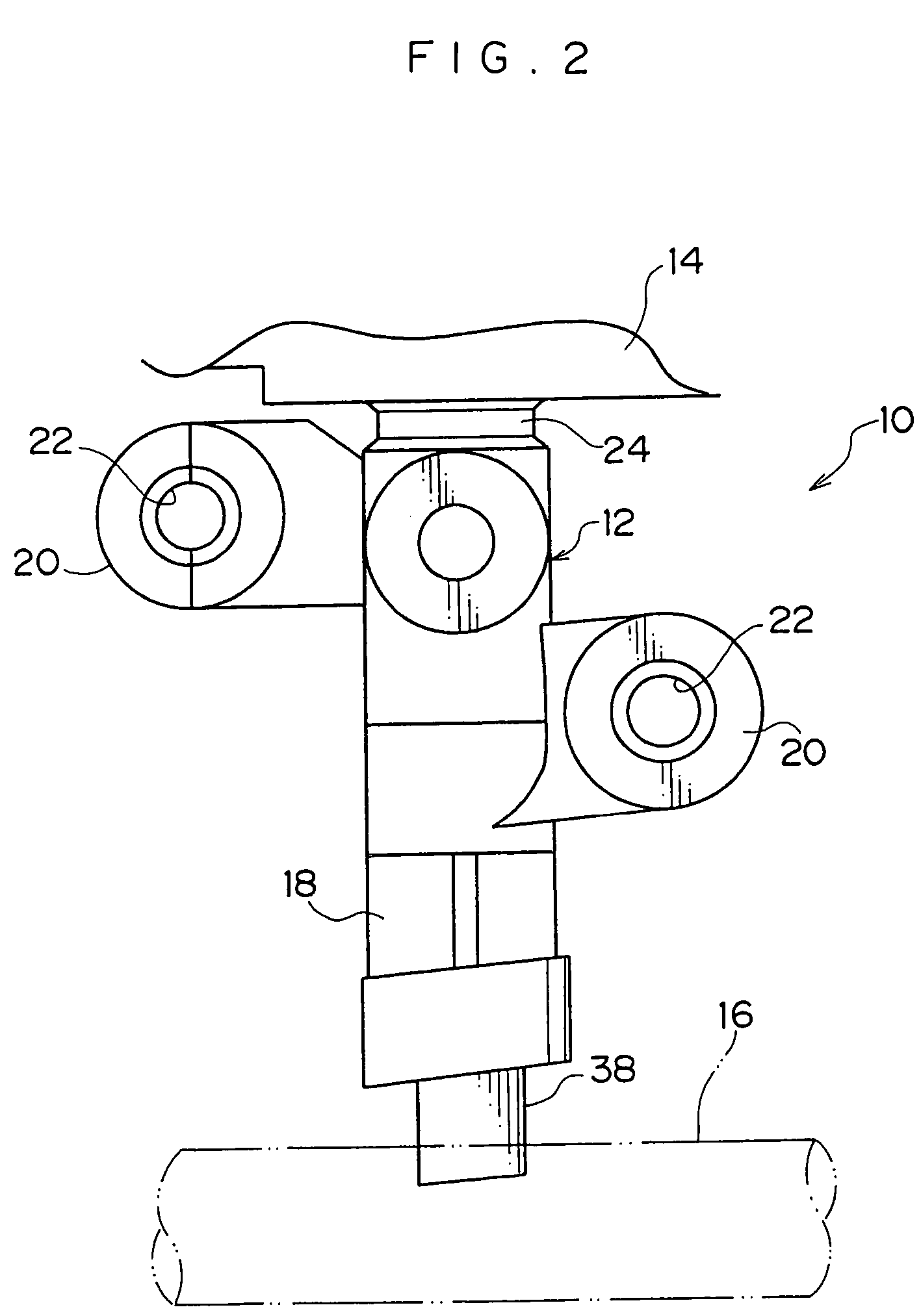
[0055]As shown in FIG. 2, mounting portions 20, which are for mounting to the steering post, project from the outer peripheral portion of the guide portion 18 at both sides in the direction parallel to the steering shaft. The lock body 12 is mounted to the steering post by being fastened to the steering post by bolts (not illustrated) being inserted through mounting holes 22 formed in the mounting portions 20.

[0056]A groove-shaped connecting portion...


PUM


Abstract

An electrically-driven steering lock device is provided having a lock body that, if broken while a vehicle is parked, the lock body is divided into a main body portion and a guide portion. A lock pin is inserted through a through-hole of a movable plate and fits into a fit-in hole formed in a lock stopper such that movement of the lock stopper is impeded. A locked state of a steering shaft is thereby maintained. Further, movement of the movable plate in a direction of being pulled-out also is impeded by the lock pin, and an interior of the guide portion is prevented from being exposed. Moreover, the lock pin is provided within the guide portion, and even if the guide portion is viewed from an exterior, it is difficult to learn of a mechanism and a position of the lock pin. Therefore, it is difficult to cancel a locked state. Thus an electrically-driven steering lock device is provided in which it is difficult to cancel the locked state by an illegal act, and which has a good antitheft quality.

Description

CROSS-REFERENCE TO RELATED APPLICATION[0001]This application claims priority under 35 USC 119 from Japanese Patent Application No. 2003-24681, the disclosures of which are incorporated by reference herein.BACKGROUND OF THE INVENTION[0002]1. Field of the Invention[0003]The present invention relates to an electrically-driven steering lock device which is applied to a vehicle such as an automobile or the like.[0004]2. Description of the Related Art[0005]Vehicles such as automobiles and the like are equipped with, for example, a so-called electrically-driven steering lock device as an antitheft device. The electrically-driven steering lock device has, for example, a lock body which is assembled to the steering post of a vehicle. The lock body has a main body portion, which houses a driving means, and a guide portion, which is tubular and projects from the main body portion toward the steering shaft. The main body portion and the guide portion are integral. Within the main body portion, ...

Claims


Application Information

Patent Timeline
Patent Type & Authority Patents(United States)
IPC IPC(8): B60R25/02B60R25/0215
CPCB60R25/02153Y10T70/5664Y10T70/5956
Inventor SUZUKI, NORIYUKIOKUNO, MASANARIFUKATSU, TOMOHIRO
Owner KK TOKAI RIKA DENKI SEISAKUSHO
Learn More