Fluid delivery control system

a control system and internal combustion engine technology, applied in the direction of machine/engine, engine revolution, lubrication of auxiliaries, etc., can solve the problems of increased force on the engine bearing, increased wear of the engine bearing, and insufficient measurement method of sensing engine rpm

Inactive Publication Date: 2006-06-06
CATERPILLAR INC
View PDF26 Cites 45 Cited by
  • Summary
  • Abstract
  • Description
  • Claims
  • Application Information

AI Technical Summary

Benefits of technology

[0010]In accordance with another aspect of the disclosure, an electric pump control system controls delivery of fluid to an engine. A pump is arranged to pump fluid to an engine. An electric

Problems solved by technology

Sensing engine RPM is often an inadequate method for determining the load on an engine and for determining the lubrication requirements of the engine.
The torque on the truck engine traveling uphill will be much higher and, consequently, there will be more force exerted on the engine bea

Method used


Image

  • Fluid delivery control system
  • Fluid delivery control system
  • Fluid delivery control system

Examples


Embodiment Construction

[0019]Reference will now be made in detail to the exemplary embodiments of the invention which are illustrated in the accompanying drawings. Wherever possible, the same reference numbers will be used throughout the drawings to refer to the same or like parts.

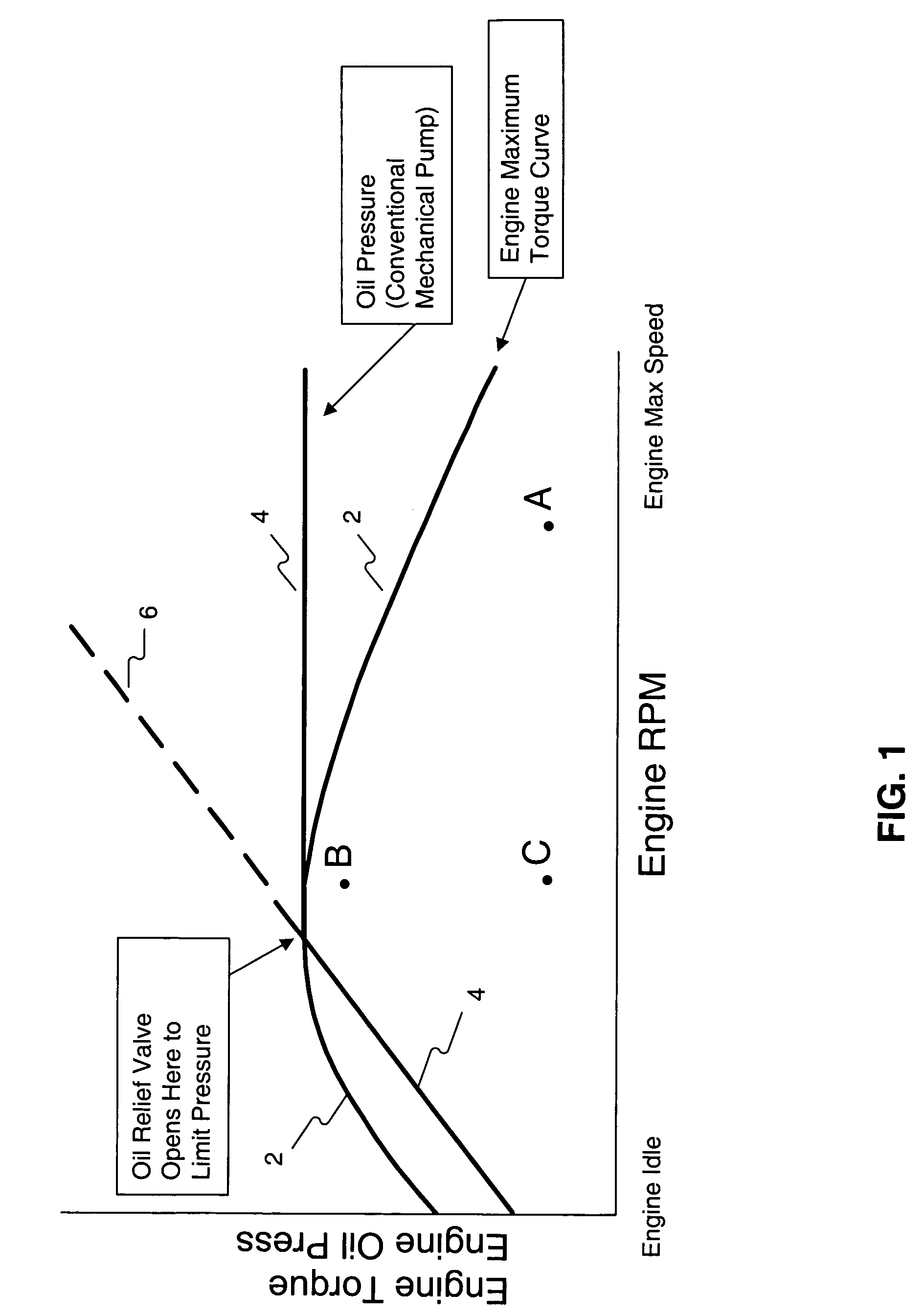
[0020]FIG. 1 depicts a set of curves illustrating the relationship between maximum engine torque and the engine oil pressure provided by a conventional mechanical oil pump. Maximum engine torque curve 2 illustrates the maximum engine torque that can be provided by a particular engine as a function of engine RPM. As engine RPM increases from an idle condition, the maximum engine torque initially increases until it reaches a peak and then decreases as engine RPM further increases.

[0021]As mentioned previously, a conventional internal combustion engine is typically lubricated with a mechanical oil pump powered by the engine via belts or gears. The mechanical oil pump speed is thus proportional to engine speed. Curve 4 illustrates t...


PUM


Abstract

A method of controlling the delivery of fluid to an engine includes receiving a fuel flow rate signal. An electric pump is arranged to deliver fluid to the engine. The speed of the electric pump is controlled based on the fuel flow rate signal.

Description

CLAIM FOR PRIORITY[0001]This application claims the benefit of U.S. Provisional Application No. 60 / 458,460, filed Mar. 28, 2003.U.S. GOVERNMENT RIGHTS[0002]This invention was made with government support under the terms of Contract No. DE-FC04-2000AL67017 awarded by the Department of Energy. The government may have certain rights in this invention.TECHNICAL FIELD[0003]This invention relates generally to fluid delivery systems for internal combustion engines, and more particularly to control systems for controlling fluid delivery to internal combustion engines.BACKGROUND[0004]Conventional internal combustion engines are typically lubricated with a mechanical pump powered by the engine via belts or gears. The speed of the pump, and therefore the oil pressure and rate of oil flow, are a function of the engine speed. Auxiliary electrically operated oil pumps have been used to operate at engine start-up to ensure oil flow to the engine as soon as possible.[0005]Oil not only lubricates en...

Claims


Application Information

Patent Timeline
IPC IPC(8): F01M1/00F01M1/02F01M1/16
CPCF01M1/16F01M5/025F01M2001/0215F01M2250/64F01M2250/60F01M2250/62F01M2005/026
Inventor HOFF, BRIAN D.JOHNSON, KRIS WILLIAMALGRAIN, MARCELO C.AKASAM, SIVAPRASAD
Owner CATERPILLAR INC
Why Eureka
Try Eureka