Device and system for dispensing or aspirating/dispensing liquid samples
a liquid sample and liquid technology, applied in liquid dispensing, chemical libraries, combinational chemistry, etc., can solve the problem of limiting the resolution of the quantity of liquid to be dispensed
- Summary
- Abstract
- Description
- Claims
- Application Information
AI Technical Summary
Problems solved by technology
Method used
Image
Examples
first embodiment
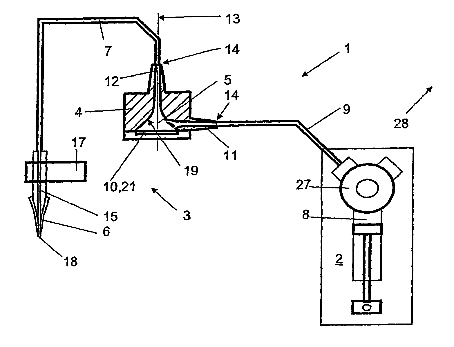
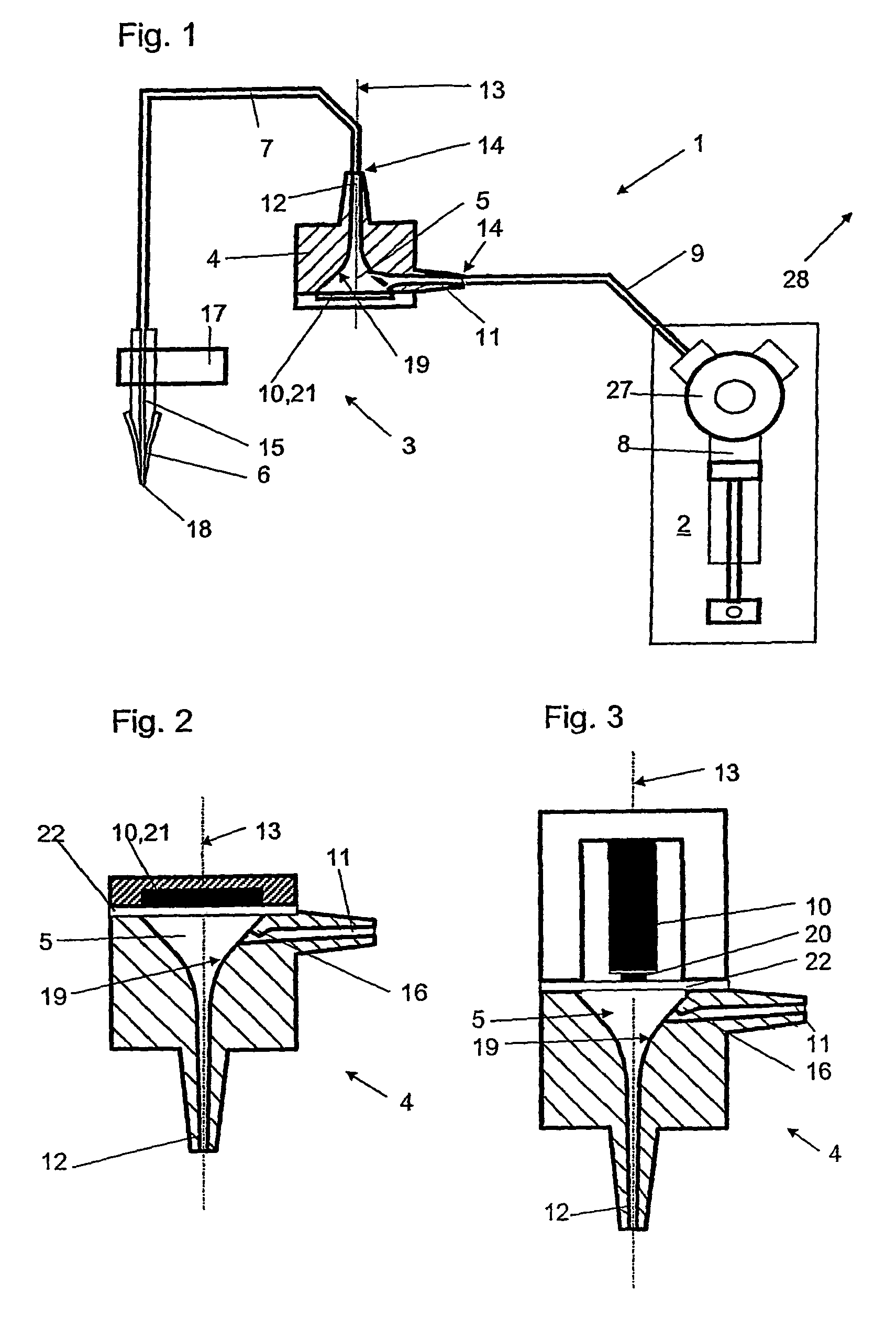
[0019]FIG. 1 shows a diagrammatic view of a device for dispensing or aspirating / dispensing liquid samples according to a Said device 1 comprises a pump 2 and a micro-ejection apparatus 3. The micro-ejection apparatus comprises an impulse generator 4 with a chamber 5 and is filled completely with a liquid which thus forms a continuous liquid column. The impulse generator 4 is arranged in such a way that, for the purpose of producing the dispensing of liquid samples, pressure waves can be produced in the liquid. The micro-ejection apparatus 3 further comprises an end piece 6 and a liquid tubing 7. The liquid tubing 7 has a length of approx. 1 m in an embodiment and connects the impulse generator 4 with the end piece 6. The inside diameter of said tubing 7 is 0.8 mm in this embodiment and the wall thickness measures 0.6 mm.
[0020]Preferably, the pump 2 is a reciprocating pump or a diluter of type “CAVRO XP 3000 plus Modular Digital Pump”. The cylinder 8 of the diluter has a volume in t...
second embodiment
[0028]FIG. 3 shows a sectional view through an impulse generator 4 according to a The axis of symmetry 13 lies co-axially to the output channel 12. A micro-actuator 10 which operates on a magnetic basis is arranged at a right angle to the axis of symmetry 13. A membrane 22 for transmitting impulses onto the liquid in the chamber 5 is arranged between the actuator arranged as a solenoid 20 and the chamber 5. Said membrane 22 closes off the chamber 5 at the rear side. Instead of a solenoid working on a magnetic basis it would also be possible to use a stack of piezo-elements (not shown). The input channel 11 is provided at its transition point to the inner wall 19 of chamber 5 with a narrowed section 16.
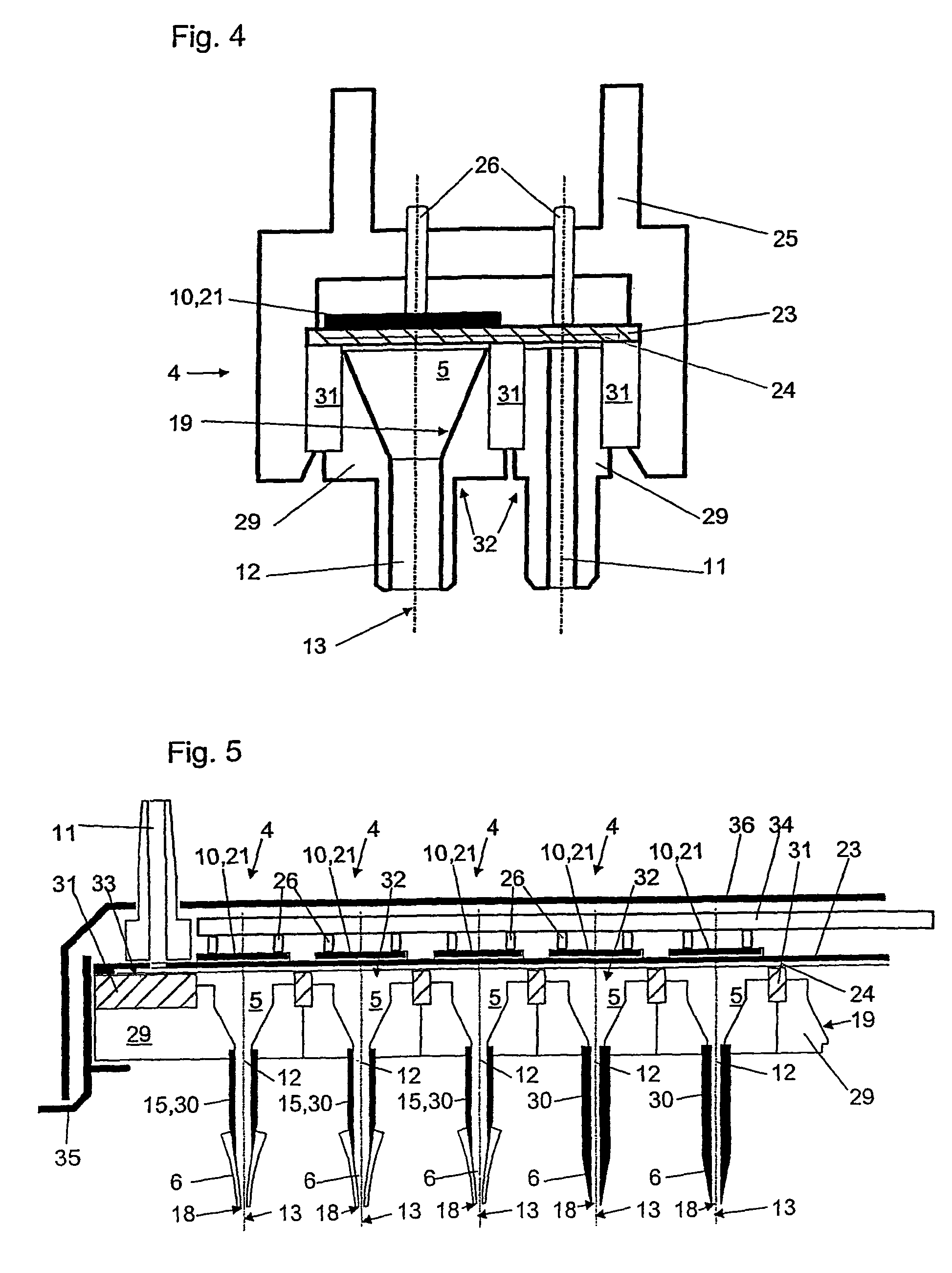
[0029]FIG. 4 shows a sectional view through an impulse generator 4 according to a third embodiment. The axis of symmetry 13 lies co-axially to the output channel 12. A piezo-element 21 is arranged as a micro-actuator 10 at a right angle to the axis of symmetry 13 and is glued onto a s...
fourth embodiment
[0034]FIG. 5 shows a sectional view through an array of impulse generators according to a The individual chambers 5 of the adjacently arranged impulse generators 4 are arranged in a component 29 which consists of a polymer material which is integrally injection-molded or turned individually from solid material for example. Needles 30 are arranged co-axially with the axis of symmetry 13 of chambers 5 and form the output channel 12 of the same. Preferably, said needles 30 consist of stainless steel and taper to a point at their free end in such a way that they can either be used directly as end pieces 6 (i.e. as pipette tips) or they each can receive a disposable tip.
[0035]In a partial or even close contact with said component 29, a compartmenting structure 31 is sealingly connected with the component 29 on its upper side. Said compartmenting structure 31 preferably consists of a glass plate from which compartments 32 are arranged in such a way that they correspond in the register wi...
PUM
| Property | Measurement | Unit |
|---|---|---|
| thickness | aaaaa | aaaaa |
| thickness | aaaaa | aaaaa |
| diameter | aaaaa | aaaaa |
Abstract
Description
Claims
Application Information
 - R&D
- Intellectual Property
- Life Sciences
- Materials
- Tech Scout
- Unparalleled Data Quality
- Higher Quality Content
- 60% Fewer Hallucinations
Browse by: Latest US Patents, China's latest patents, Technical Efficacy Thesaurus, Application Domain, Technology Topic, Popular Technical Reports.
© 2025 PatSnap. All rights reserved.Legal|Privacy policy|Modern Slavery Act Transparency Statement|Sitemap|About US| Contact US: help@patsnap.com


