Canted coil springs various designs

a coil spring and coil spring technology, applied in the direction of wound springs, springs/dampers, fastening means, etc., can solve the problems of not dominating or enabling the spring to achieve its total design potential

Active Publication Date: 2006-06-06
BAL SEAL ENG CO INC
View PDF27 Cites 150 Cited by
  • Summary
  • Abstract
  • Description
  • Claims
  • Application Information

AI Technical Summary

Benefits of technology

[0013]In various embodiments of the present invention, the secondary coils may have a smaller diameter than th

Problems solved by technology

While these parameters can be used effectively to tailor the load-deflection characteristics o

Method used


Image

  • Canted coil springs various designs
  • Canted coil springs various designs
  • Canted coil springs various designs

Examples


Embodiment Construction

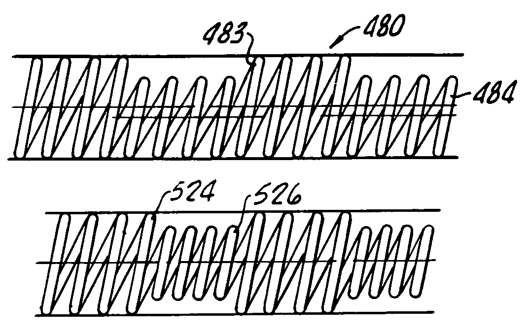
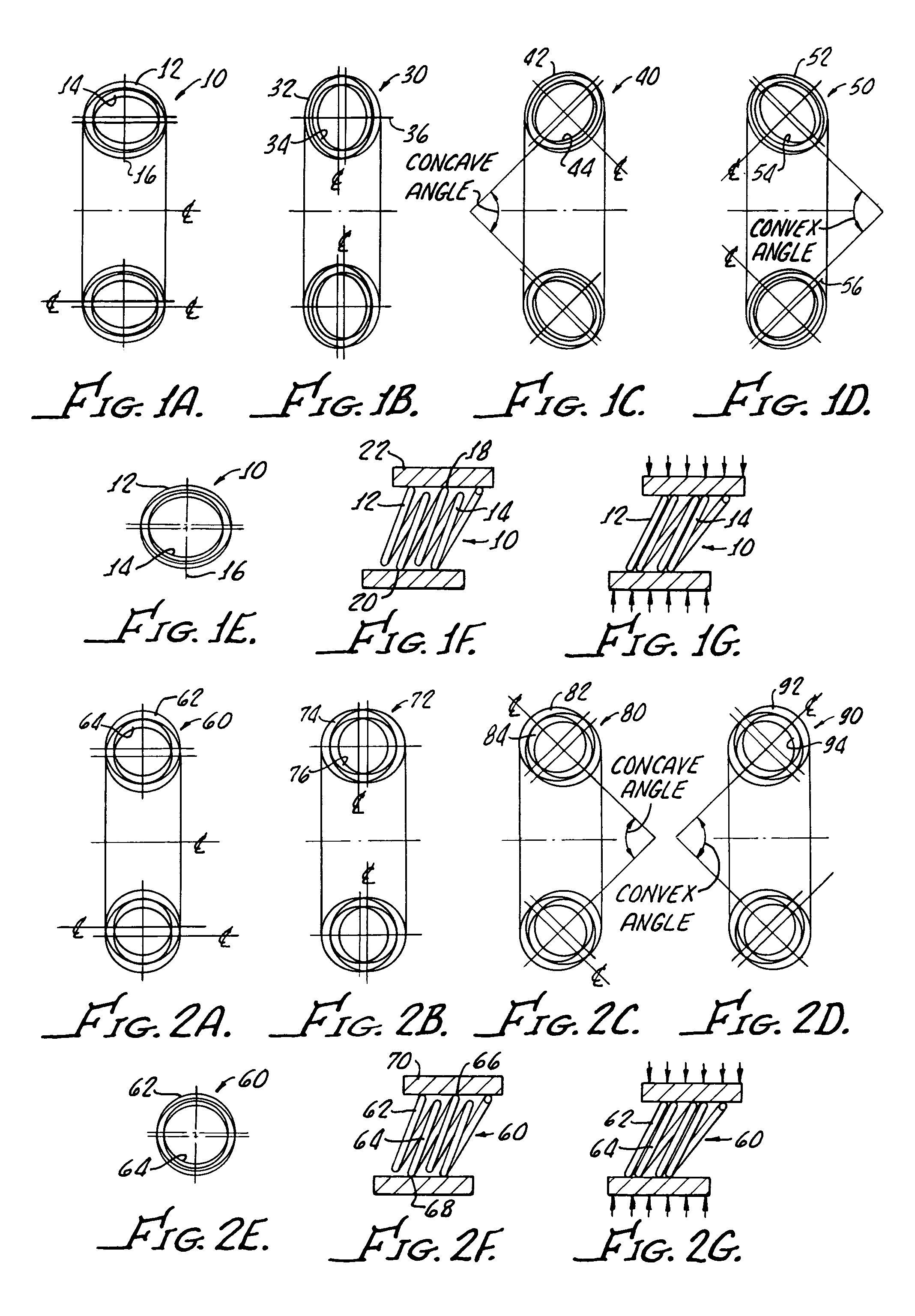
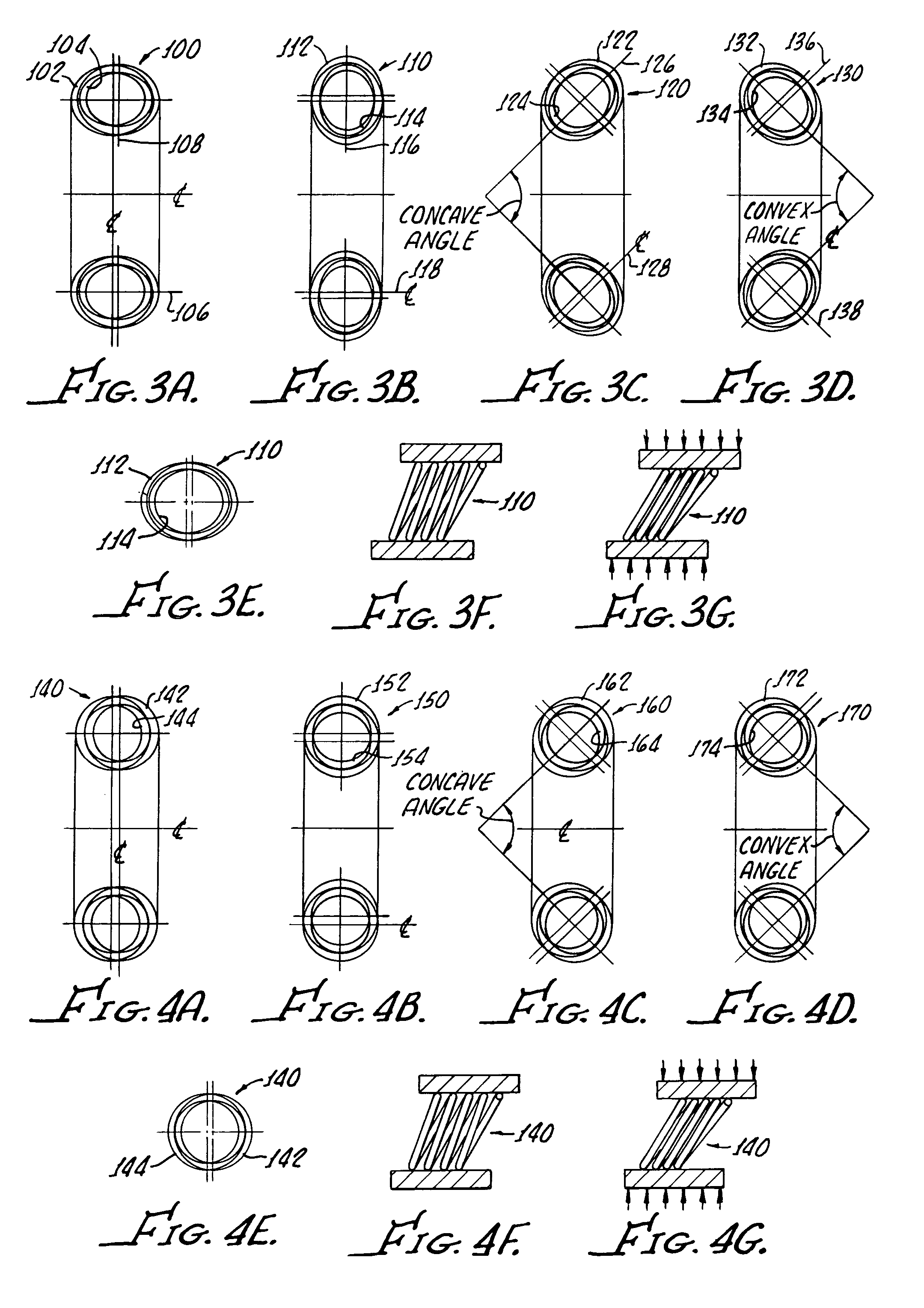
[0037]With reference to FIG. 1A, there is shown a coil spring 10 in accordance with the present invention, including a plurality of primary coils 12, and a plurality of secondary coils 14. The spring 10 is radial with the elliptical coils 12, 14 offset along the minor axis 16 and canting along the minor axis is more clearly shown in FIG. 1E. It should be appreciated that the coils 12, 14 are contiguous and formed from any conventional wire suitable for the manufacture of springs.

[0038]A longitudinal sectional view of the spring 10 is shown in FIG. 1E with the offset elliptical coils canting along the minor axis with only one side of the coils having alternate points of contact 18, 20 with a loading member 22.

[0039]FIGS. 1E–1G show that the differential size of the coils 18, 20 provide variable force and variable deflection in that the deflection force will increase upon additional contact of the coils 12, 14 upon loading, see FIG. 1F, and further, upon deflection of the coils as sho...


PUM


Abstract

A coil spring includes a plurality of primary wire coils and a plurality of secondary wire coils, the primary and secondary coils being contiguous and differentiated from one another by a dimensional size in order to provide variable force and variable deflection.

Description

[0001]This application claims the benefit of Provisional Application No. 60 / 415,244, filed Sep. 30, 2002.[0002]The present invention generally relates to canted-coil springs and more particularly, relates to canted-coil springs of various designs.[0003]A general discussion of these types of canted-coil garter-type springs and further advancement in spring design is set forth in U.S. Pat. Nos. 4,655,462; 4,826,144; 4,830,344; 4,893,795; 4,876,781; 4,907,788; 4,915,366; 4,961,253; 4,974,821; 4,964,204; 5,160,122; 5,108,078; 5,139,243; 5,139,276; 5,203,849; 5,239,737; 5,503,375; 5,615,870; 5,709,371; 5,791,638 to Balsells. All these patents are to be incorporated herein by their specific reference thereto for the purpose of disclosing heretofore coil spring design and manufacture.[0004]The force-deflection characteristics of heretofore-available garter-type axial springs have been varied by changing numerous spring parameters, including the wire size, the coil height, the coil spacing,...

Claims


Application Information

Patent Timeline
IPC IPC(8): F16F1/06F16BF16F1/04
CPCF16F1/045
Inventor BALSELLS, PETER J.
Owner BAL SEAL ENG CO INC
Why Eureka
Try Eureka